Information governor
BOSCH
9 420 611 156
9420611156
ZEXEL
105419-1760
1054191760
ISUZU
1157708720
1157708720
Rating:
Scheme ###:
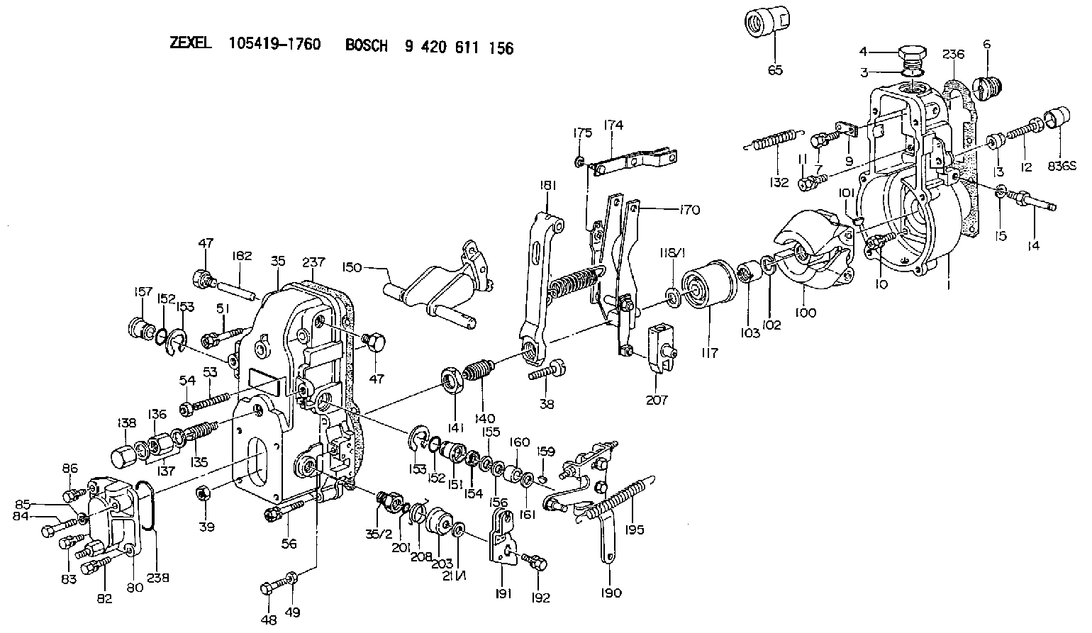
| 1. | [1] | 154000-6400 | GOVERNOR HOUSING |
| 3. | [1] | 029632-5070 | O-RING |
| 4. | [1] | 154007-2900 | CAPSULE |
| 6. | [1] | 154007-0200 | ADAPTOR |
| 7. | [1] | 020018-1840 | BLEEDER SCREW M8P1.25L18 |
| 9. | [1] | 154350-1800 | PLATE |
| 10. | [5] | 029010-6810 | BLEEDER SCREW |
| 11. | [1] | 020106-1640 | BLEEDER SCREW M6P1.0L14 |
| 12. | [1] | 154010-8100 | BLEEDER SCREW M8P1.25L65 |
| 12B. | [1] | 154010-8900 | BLEEDER SCREW M8P1.25L67.5 |
| 13. | [1] | 154011-0100 | HEXAGON NUT |
| 14. | [1] | 154012-1500 | BLEEDER SCREW |
| 15. | [1] | 014110-8440 | LOCKING WASHER |
| 35. | [1] | 154500-3720 | GOVERNOR COVER |
| 35/2. | [1] | 154321-0400 | BUSHING |
| 38. | [1] | 154031-0100 | FLAT-HEAD SCREW |
| 39. | [1] | 013020-6020 | UNION NUT M6P1H5 |
| 47. | [2] | 154036-0300 | CAPSULE |
| 47. | [2] | 154036-0300 | CAPSULE |
| 48. | [1] | 154037-0700 | BLEEDER SCREW |
| 49. | [1] | 154038-0200 | HEXAGON NUT |
| 51. | [2] | 020106-5040 | BLEEDER SCREW |
| 53. | [1] | 154010-0200 | FLAT-HEAD SCREW |
| 54. | [1] | 154011-2300 | UNION NUT |
| 56. | [4] | 020106-3840 | BLEEDER SCREW |
| 65. | [1] | 154050-6120 | STOPPING DEVICE |
| 80. | [1] | 154060-1020 | COVER |
| 82. | [1] | 020006-1640 | BLEEDER SCREW M6P1L16 4T |
| 83. | [1] | 020006-1640 | BLEEDER SCREW M6P1L16 4T |
| 84. | [1] | 029020-6220 | BLEEDER SCREW |
| 85. | [1] | 014110-6440 | LOCKING WASHER |
| 86. | [1] | 020006-1640 | BLEEDER SCREW M6P1L16 4T |
| 100. | [1] | 154101-0020 | FLYWEIGHT ASSEMBLY |
| 101. | [1] | 025803-1610 | WOODRUFF KEY |
| 102. | [1] | 029321-2020 | LOCKING WASHER |
| 103. | [1] | 029231-2030 | UNION NUT |
| 117. | [1] | 154123-0120 | SLIDING PIECE |
| 118/1. | [0] | 029311-0010 | SHIM D14&10.1T0.2 |
| 118/1. | [0] | 029311-0180 | SHIM D14&10.1T0.3 |
| 118/1. | [0] | 029311-0190 | SHIM D14&10.1T0.40 |
| 118/1. | [0] | 029311-0210 | SHIM D14&10.1T1 |
| 118/1. | [0] | 139410-0000 | SHIM D14.0&10.1T0.5 |
| 118/1. | [0] | 139410-0100 | SHIM D14.0&10.1T1.5 |
| 118/1. | [0] | 139410-3000 | SHIM D14&10.1T2.0 |
| 118/1. | [0] | 139410-3100 | SHIM D14&10.1T3.0 |
| 118/1. | [0] | 139410-3200 | SHIM D14&10.1T4.0 |
| 132. | [1] | 154154-0701 | COILED SPRING |
| 135. | [1] | 154158-1320 | HEADLESS SCREW |
| 136. | [1] | 154011-1700 | UNION NUT |
| 137. | [2] | 026512-1540 | GASKET D15.4&12.2T1.50 |
| 138. | [1] | 154159-1200 | CAP NUT |
| 140. | [1] | 154185-4020 | HEADLESS SCREW |
| 141. | [1] | 029201-6010 | UNION NUT |
| 150. | [1] | 154200-7220 | SWIVELLING LEVER |
| 151. | [1] | 154204-4300 | BUSHING |
| 152. | [2] | 029631-8020 | O-RING |
| 152. | [2] | 029631-8020 | O-RING |
| 153. | [2] | 016010-1640 | LOCKING WASHER |
| 153. | [2] | 016010-1640 | LOCKING WASHER |
| 154. | [1] | 139611-0000 | PACKING RING |
| 155. | [1] | 139411-0000 | SHIM |
| 156. | [0] | 029311-1070 | SHIM D16&11T0.5 |
| 157. | [1] | 154204-4400 | BUSHING |
| 159. | [1] | 025803-1310 | WOODRUFF KEY |
| 160. | [1] | 154206-2800 | BUSHING |
| 161. | [0] | 154206-0200 | PLAIN WASHER D19.5&11.2T1.0 |
| 170. | [1] | 154210-7420 | FORK LEVER |
| 174. | [1] | 154230-3920 | STRAP |
| 175. | [1] | 016010-0540 | LOCKING WASHER |
| 181. | [1] | 154239-1720 | TENSIONING LEVER |
| 182. | [1] | 154237-0100 | BEARING PIN |
| 190. | [1] | 154349-5120 | CONTROL LEVER |
| 191. | [1] | 154380-5320 | CONTROL LEVER |
| 192. | [1] | 020006-1640 | BLEEDER SCREW M6P1L16 4T |
| 195. | [1] | 154314-0200 | COILED SPRING |
| 201. | [1] | 029631-0030 | O-RING &9.8W2.3 |
| 203. | [1] | 154322-0100 | CAP |
| 207. | [1] | 154326-5120 | CONTROL LEVER |
| 208. | [1] | 154327-7300 | COILED SPRING |
| 211/1. | [0] | 029311-0520 | SHIM D20.8&10.3T0.2 |
| 211/1. | [0] | 029311-0530 | SHIM D20.8&10.3T0.25 |
| 211/1. | [0] | 029311-0540 | SHIM D20.8&10.3T0.3 |
| 211/1. | [0] | 029311-0550 | SHIM D20.8&10.3T0.35 |
| 211/1. | [0] | 029311-0560 | SHIM D20.8&10.3T0.4 |
| 211/1. | [0] | 029311-0570 | SHIM D20.8&10.3T0.5 |
| 236. | [1] | 154390-0000 | GASKET |
| 237. | [1] | 154390-0300 | GASKET |
| 238. | [1] | 029635-2020 | O-RING |
| 836S. | [1] | 154062-1700 | CAP D20L32 |
Include in #1:
101602-7730
as GOVERNOR
Cross reference number
Zexel num
Bosch num
Firm num
Name
105419-1760
1157708720 ISUZU
GOVERNOR
K 14JB MECHANICAL GOVERNOR GOV RSV GOV
K 14JB MECHANICAL GOVERNOR GOV RSV GOV
Information:
After the engine starts, and at frequent intervals while the engine is operating, the gauges should be observed. Determine the normal reading for each gauge. Investigate the cause whenever there is a significant change in the reading.Gauges
Tachometer
The tachometer indicates engine RPM. The high idle RPM and the full load RPM are stamped on the engine's information plate. The engine can be operated between these two speed limits for long periods of time without shortening engine life. Prolonged operation at high idle with little or no load can cause adverse engine operation. Engine Oil Pressure
If the gauge reading fluctuates after the load is stable:1. Remove the load.2. Reduce engine speed to low idle.3. Observe the oil level. Maintain the oil level between the ADD and FULL mark on the dipstick. If the reading continues to fluctuate when the oil level is correct, stop engine and call your Caterpillar dealer. Engine Jacket Water Temperature
The engine should operate within the NORMAL (green) range. If the engine is operating in the (red) range and steam becomes apparent:1. Reduce the load and engine RPM.2. Inspect for coolant leaks.3. Determine if the engine must be shut down immediately; or if the engine can be safely cooled by reducing the load.See COOLING SYSTEM MAINTENANCE INSTRUCTIONS.
Do not add cold water to a hot engine: Cracking of engine components may occur. Allow the engine to cool, then add coolant.
If the temperature gauge reading registers in or near the cold range (white) while operating under load:1. Check the water temperature gauge for accuracy.2. Check the temperature regulators for proper temperature range. Replace regulators if necessary.See COOLING SYSTEM MAINTENANCE for DETAILS. Fuel pressure
If the fuel filter gauge registers in the OUT range, clean the primary fuel filter, if so equipped. Install new secondary or final fuel filter elements if gauge still registers OUT. See the FUEL MAINTENANCE INSTRUCTIONS and FUEL SPECIFICATIONS. Ammeter:
The ammeter reading is normal when the indicator is at or on the (+) side of zero, when the engine is running at rated speed. If indicator is to the left (-) side of zero, investigate and correct cause. Air Cleaner Service Indicator
When the gauge indicator locks in the red range, service the air cleaner. With the engine stopped; see AIR INDUCTION AND EXHAUST SYSTEM MAINTENANCE INSTRUCTIONS. Calibrated Gauges
Calibrated gauges are used on some engines to monitor the engine systems. If an abnormal engine condition develops, determine and analyze and correct the cause before a failure and downtime occurs.The operating limits given in the "OPERATING RANGES FOR ENGINES" chart are based on the engine running at continuous rated speed and load, after warm-up, using SAE 30, oil. If any of the gauges register at or outside the operating limits, investigate and correct any malfunction. See TROUBLESHOOTING GUIDE for guidance.
Shut the engine down if work on or around the engine is required.
DO NOT OPERATE THE ENGINE WITH THE GAUGES REGISTERING AT OR OUTSIDE THE LIMITS.
1. Tachometer.2. Left inlet manifold temperature.3. Right inlet manifold temperature.4. Left and right exhaust manifold