Information governor
BOSCH
F 019 Z1E 151
f019z1e151
ZEXEL
105419-1510
1054191510
ISUZU
8971143350
8971143350

Rating:
Scheme ###:
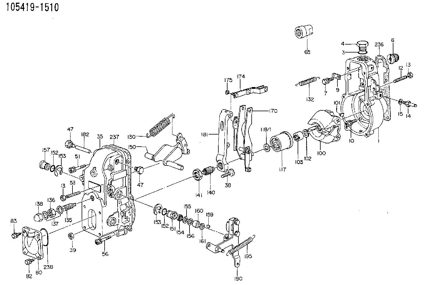
| 1. | [1] | 154000-6400 | GOVERNOR HOUSING |
| 3. | [1] | 029632-5070 | O-RING |
| 4. | [1] | 154007-2900 | CAPSULE |
| 6. | [1] | 154007-0200 | ADAPTOR |
| 7. | [1] | 020018-1840 | BLEEDER SCREW M8P1.25L18 |
| 9. | [1] | 154350-1900 | PLATE |
| 10. | [6] | 029010-6810 | BLEEDER SCREW |
| 12. | [1] | 154010-0100 | FLAT-HEAD SCREW |
| 13. | [2] | 154011-0100 | HEXAGON NUT |
| 13. | [2] | 154011-0100 | HEXAGON NUT |
| 14. | [1] | 154012-1500 | BLEEDER SCREW |
| 15. | [1] | 014110-8440 | LOCKING WASHER |
| 35. | [1] | 154500-2020 | GOVERNOR COVER |
| 38. | [1] | 154031-0100 | FLAT-HEAD SCREW |
| 39. | [1] | 013020-6020 | UNION NUT M6P1H5 |
| 47. | [2] | 154036-0300 | CAPSULE |
| 47. | [2] | 154036-0300 | CAPSULE |
| 51. | [2] | 020106-5040 | BLEEDER SCREW |
| 53. | [1] | 154010-0100 | FLAT-HEAD SCREW |
| 56. | [4] | 020106-3840 | BLEEDER SCREW |
| 65. | [1] | 155404-0200 | CAP |
| 80. | [1] | 154063-1800 | COVER |
| 82. | [2] | 029020-6210 | BLEEDER SCREW |
| 83. | [2] | 020006-1640 | BLEEDER SCREW M6P1L16 4T |
| 100. | [1] | 154100-3220 | FLYWEIGHT ASSEMBLY |
| 101. | [1] | 025803-1610 | WOODRUFF KEY |
| 102. | [1] | 029321-2020 | LOCKING WASHER |
| 103. | [1] | 029231-2030 | UNION NUT |
| 117. | [1] | 154123-0120 | SLIDING PIECE |
| 118/1. | [0] | 029311-0010 | SHIM D14&10.1T0.2 |
| 118/1. | [0] | 029311-0180 | SHIM D14&10.1T0.3 |
| 118/1. | [0] | 029311-0190 | SHIM D14&10.1T0.40 |
| 118/1. | [0] | 029311-0210 | SHIM D14&10.1T1 |
| 118/1. | [0] | 139410-0000 | SHIM D14.0&10.1T0.5 |
| 118/1. | [0] | 139410-0100 | SHIM D14.0&10.1T1.5 |
| 118/1. | [0] | 139410-3000 | SHIM D14&10.1T2.0 |
| 118/1. | [0] | 139410-3100 | SHIM D14&10.1T3.0 |
| 118/1. | [0] | 139410-3200 | SHIM D14&10.1T4.0 |
| 130. | [1] | 154150-2700 | GOVERNOR SPRING |
| 132. | [1] | 154154-4100 | COILED SPRING |
| 135. | [1] | 154157-5220 | HEADLESS SCREW |
| 136. | [1] | 029201-2030 | UNION NUT M12P1.0H4 |
| 137. | [2] | 026512-1540 | GASKET D15.4&12.2T1.50 |
| 138. | [1] | 154159-0100 | CAP NUT |
| 140. | [1] | 154175-5020 | HEADLESS SCREW |
| 141. | [1] | 029201-6010 | UNION NUT |
| 150. | [1] | 154200-7220 | SWIVELLING LEVER |
| 151. | [1] | 154204-3000 | BUSHING |
| 152. | [2] | 029631-8020 | O-RING |
| 152. | [2] | 029631-8020 | O-RING |
| 153. | [2] | 016010-1640 | LOCKING WASHER |
| 153. | [2] | 016010-1640 | LOCKING WASHER |
| 154. | [1] | 139611-0000 | PACKING RING |
| 155. | [1] | 139411-0000 | SHIM |
| 156. | [0] | 029311-1090 | SHIM D16&11T0.3 |
| 157. | [1] | 154204-3100 | BUSHING |
| 159. | [1] | 025803-1310 | WOODRUFF KEY |
| 160. | [1] | 154206-2800 | BUSHING |
| 161. | [0] | 154206-0200 | PLAIN WASHER D19.5&11.2T1.0 |
| 170. | [1] | 154211-3820 | FORK LEVER |
| 174. | [1] | 154230-0120 | STRAP |
| 175. | [1] | 016010-0540 | LOCKING WASHER |
| 181. | [1] | 154236-1500 | TENSIONING LEVER |
| 182. | [1] | 154237-0100 | BEARING PIN |
| 190. | [1] | 154303-5220 | CONTROL LEVER |
| 195. | [1] | 154314-0200 | COILED SPRING |
| 236. | [1] | 154390-0000 | GASKET |
| 237. | [1] | 154390-0300 | GASKET |
| 238. | [1] | 029635-2020 | O-RING |
Include in #1:
101431-4210
as GOVERNOR
Cross reference number
Zexel num
Bosch num
Firm num
Name
Information:
Start By:a. remove valve coversb. remove fuel injection lines 1. Use tool (A) and a 5P328 crowfoot wrench (7/8") to loosen the fuel injection line nut at the nozzle end.
Do not let the tops of the fuel nozzles turn when the fuel lines are loosened. The nozzles will be damaged if the top of the nozzles turn in the body.
2. Use tool (B) to loosen the nut at the fuel injection line adapter end. Remove inner fuel injection lines (1). Install plugs in the fuel injection nozzles. 3. Remove the nut that holds the adapters to the cylinder head assembly. Remove fuel injection line adapters (2).Install Fuel Injection Line Adapters
1. Check the condition of O-ring seal (1) on fuel injection line adapter (2) for damage. Make a replacement if necessary.2. Lubricate O-ring seal (1) with clean engine oil. Install fuel injection line adapter (2). Tighten the retaining nut to a torque of 13.6 2.7 N m (10 2 lb ft). 3. Check the condition of the O-ring seal on inner fuel line (3) for damage, and make a replacement if necessary. Install inner fuel line (3).
Do not let the tops of the fuel nozzles turn when the fuel lines are tightened. The nozzles will be damaged if the top of the nozzles turn in the body.
4. Use tooling (A) to tighten the inner fuel line nuts to a torque of 42 6.8 N m (32 5 lb ft).End By:a. install fuel injection linesb. install valve covers