Information governor
BOSCH
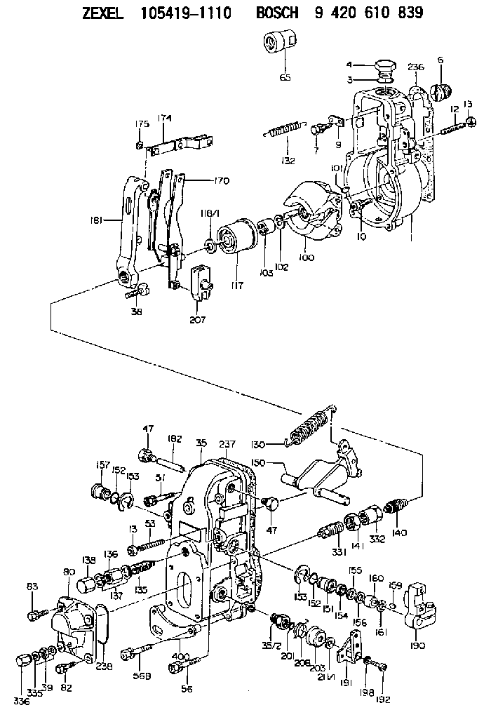
9 420 610 839
9420610839
ZEXEL
105419-1110
1054191110
Rating:
Scheme ###:
| 1. | [1] | 154000-6400 | GOVERNOR HOUSING |
| 3. | [1] | 029632-5070 | O-RING |
| 4. | [1] | 154007-2900 | CAPSULE |
| 6. | [1] | 154007-0200 | ADAPTOR |
| 7. | [1] | 020018-1840 | BLEEDER SCREW M8P1.25L18 |
| 9. | [1] | 154350-1900 | PLATE |
| 10. | [6] | 029010-6810 | BLEEDER SCREW |
| 12. | [1] | 154010-0100 | FLAT-HEAD SCREW |
| 13. | [2] | 154011-0100 | HEXAGON NUT |
| 13. | [2] | 154011-0100 | HEXAGON NUT |
| 35. | [1] | 154500-3020 | GOVERNOR COVER |
| 35/2. | [1] | 154321-0400 | BUSHING |
| 38. | [1] | 154031-3000 | FLAT-HEAD SCREW |
| 39. | [1] | 139206-0600 | UNION NUT |
| 47. | [2] | 154036-0300 | CAPSULE |
| 47. | [2] | 154036-0300 | CAPSULE |
| 51. | [2] | 020106-5040 | BLEEDER SCREW |
| 53. | [1] | 154010-0100 | FLAT-HEAD SCREW |
| 56. | [2] | 020106-3840 | BLEEDER SCREW |
| 56B. | [2] | 139006-8500 | BLEEDER SCREW |
| 65. | [1] | 154050-1720 | STOPPING DEVICE |
| 80. | [1] | 154064-0400 | COVER |
| 82. | [2] | 029020-6210 | BLEEDER SCREW |
| 83. | [2] | 020006-1640 | BLEEDER SCREW M6P1L16 4T |
| 100. | [1] | 154100-9720 | FLYWEIGHT ASSEMBLY |
| 101. | [1] | 025803-1610 | WOODRUFF KEY |
| 102. | [1] | 029321-2020 | LOCKING WASHER |
| 103. | [1] | 029231-2030 | UNION NUT |
| 117. | [1] | 154123-0120 | SLIDING PIECE |
| 118/1. | [0] | 029311-0010 | SHIM D14&10.1T0.2 |
| 118/1. | [0] | 029311-0180 | SHIM D14&10.1T0.3 |
| 118/1. | [0] | 029311-0190 | SHIM D14&10.1T0.40 |
| 118/1. | [0] | 029311-0210 | SHIM D14&10.1T1 |
| 118/1. | [0] | 139410-0000 | SHIM D14.0&10.1T0.5 |
| 118/1. | [0] | 139410-0100 | SHIM D14.0&10.1T1.5 |
| 118/1. | [0] | 139410-3000 | SHIM D14&10.1T2.0 |
| 118/1. | [0] | 139410-3100 | SHIM D14&10.1T3.0 |
| 118/1. | [0] | 139410-3200 | SHIM D14&10.1T4.0 |
| 130. | [1] | 154150-6400 | GOVERNOR SPRING |
| 132. | [1] | 154154-0800 | COILED SPRING |
| 135. | [1] | 154158-1820 | HEADLESS SCREW |
| 136. | [1] | 154011-1700 | UNION NUT |
| 137. | [2] | 026512-1540 | GASKET D15.4&12.2T1.50 |
| 138. | [1] | 154159-1200 | CAP NUT |
| 140. | [1] | 154185-1320 | HEADLESS SCREW |
| 141. | [1] | 029201-6080 | UNION NUT |
| 150. | [1] | 154200-6920 | SWIVELLING LEVER |
| 151. | [1] | 154204-3000 | BUSHING |
| 152. | [2] | 029631-8020 | O-RING |
| 152. | [2] | 029631-8020 | O-RING |
| 153. | [2] | 016010-1640 | LOCKING WASHER |
| 153. | [2] | 016010-1640 | LOCKING WASHER |
| 154. | [1] | 139611-0000 | PACKING RING |
| 155. | [1] | 139411-0000 | SHIM |
| 156. | [0] | 029311-1070 | SHIM D16&11T0.5 |
| 157. | [1] | 154204-3100 | BUSHING |
| 159. | [1] | 025803-1310 | WOODRUFF KEY |
| 160. | [1] | 154206-2800 | BUSHING |
| 161. | [0] | 154206-0200 | PLAIN WASHER D19.5&11.2T1.0 |
| 170. | [1] | 154210-0820 | FORK LEVER |
| 174. | [1] | 154230-3920 | STRAP |
| 175. | [1] | 016010-0540 | LOCKING WASHER |
| 181. | [1] | 154236-4100 | TENSIONING LEVER |
| 182. | [1] | 154237-0100 | BEARING PIN |
| 190. | [1] | 154340-2020 | CONTROL LEVER |
| 191. | [1] | 154364-7520 | CONTROL LEVER |
| 192. | [1] | 010206-1440 | HEX-SOCKET-HEAD CAP SCREW M6P1L14 |
| 198. | [1] | 029320-6010 | LOCKING WASHER |
| 201. | [1] | 029631-0030 | O-RING &9.8W2.3 |
| 203. | [1] | 154322-0100 | CAP |
| 207. | [1] | 154326-5120 | CONTROL LEVER |
| 208. | [1] | 154327-7300 | COILED SPRING |
| 211/1. | [0] | 029311-0520 | SHIM D20.8&10.3T0.2 |
| 211/1. | [0] | 029311-0530 | SHIM D20.8&10.3T0.25 |
| 211/1. | [0] | 029311-0540 | SHIM D20.8&10.3T0.3 |
| 211/1. | [0] | 029311-0550 | SHIM D20.8&10.3T0.35 |
| 211/1. | [0] | 029311-0560 | SHIM D20.8&10.3T0.4 |
| 211/1. | [0] | 029311-0570 | SHIM D20.8&10.3T0.5 |
| 236. | [1] | 154390-0000 | GASKET |
| 237. | [1] | 154390-0300 | GASKET |
| 238. | [1] | 029635-2020 | O-RING |
| 331. | [1] | 154179-1820 | HEADLESS SCREW |
| 332. | [1] | 029201-6010 | UNION NUT |
| 335. | [2] | 026506-1040 | GASKET D9.9&6.2T1 |
| 336. | [1] | 154035-1600 | CAP NUT |
| 400. | [1] | 154371-9620 | BRACKET |
Cross reference number
Zexel num
Bosch num
Firm num
Name
Information:
Start By:a. remove fuel injection lines
Keep all parts clean from contaminants. Contaminants put into the system may cause rapid wear and shortened component life.
1. Remove bolts (1) and fan guard (2). 2. Loosen bolts (7), (9) and (10). Remove belts (8).3. Remove bolt (4) to clip. Remove grease line (3).4. Remove nuts (6). Remove cover (5) and the gasket. 5. Loosen bolt (12) enough to leave a gap of 3.18 mm (.125 in) between washers (11) and the fuel pump drive gear.6. Install tool (A) as shown. Tighten the stud to pull the fuel pump drive gear loose from the taper on the fuel injection pump camshaft.7. Remove tool (A), bolt (12), and washer (11). 8. Identify and disconnect wires (13).9. Remove tube assemblies (15) and (18).10. Remove two bolts (14), fuel transfer pump (17), and the O-ring seal.11. Remove bolts (16), the filter base, the gasket, and filter (19). 12. Fasten the fuel injection pump housing and governor to a hoist.13. Remove two bolts (22), three nuts (21), and the fuel injection pump housing and governor. The weight of the fuel injection pump housing and governor is 29 kg (64 lb.).14. Remove the two O-ring seals from the bottom of the fuel injection pump housing and governor. 15. Loosen screw (25). Remove two screws (26), control assembly (23) and spacers (24).Install Fuel Injection Pump Housing And Governor
Start By:a. remove fuel injection linesb. remove valve cover Number 1 piston must be set at top dead center (TDC) to perform all timing procedures. The engine is seen from the flywheel end when direction of crankshaft rotation is given. 1. Remove the starter.2. Install tool (B) on flywheel housing as shown.3. To find TDC for No. 1 piston;a. Turn the flywheel clockwise (opposite the direction of engine rotation) approximately 30 degrees. This removes all play from the timing gears. If you go past the bolt hole, you must repeat Step (a).b. Turn the flywheel counterclockwise until a 3/8" - 16 x 2 1/4" NC bolt (27) can be installed in the flywheel through the hole in the flywheel housing. The No. 1 and No. 6 pistons are now at top center position. The No. 1 piston is on the compression stroke when the valves of the No. 1 cylinder are closed. The rocker must be free to move up and down.4. If No. 1 piston is not on the compression stroke, remove the 3/8" - 16 x 2 1/4" NC bolt (27) and turn the flywheel 360° counterclockwise. Install the 3/8" bolt as before. The No. 1 piston is now at TDC.
Typical Example5. Install tooling (C) in the fuel injection pump housing as shown. Push on tooling (C) and turn injection pump camshaft (32). When tooling (C) engages the groove (slot) in the camshaft, the fuel injection pump is in the No. 1 piston TDC position.6. Be sure O-ring seals (28), (29), (30) and (31) are in position on the fuel injection pump housing and governor. Put clean engine oil