Information governor
BOSCH
9 420 612 871
9420612871
ZEXEL
105419-0710
1054190710
ISUZU
1157705220
1157705220
Rating:
Scheme ###:
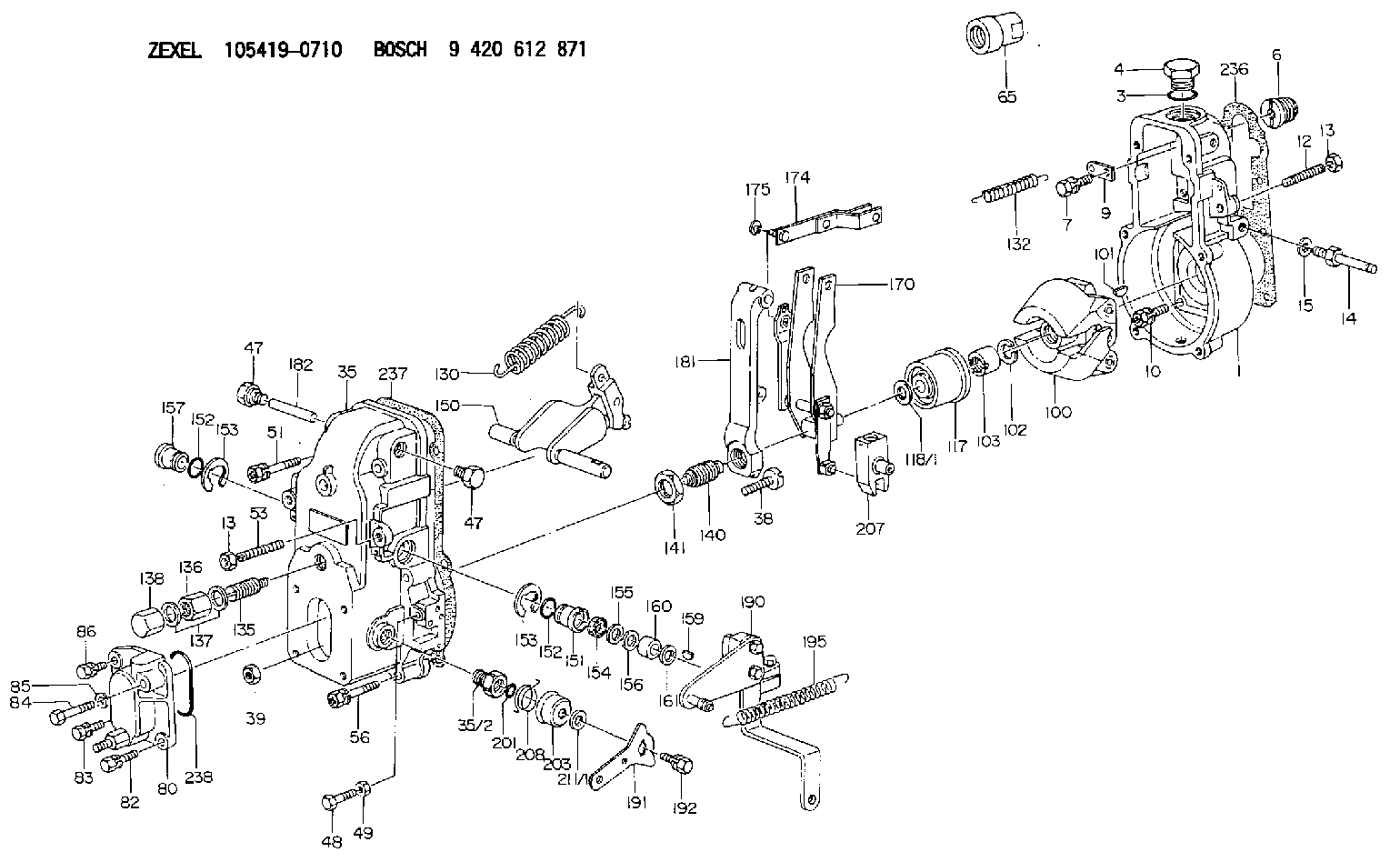
| 1. | [1] | 154000-6400 | GOVERNOR HOUSING |
| 3. | [1] | 029632-5070 | O-RING |
| 4. | [1] | 154007-2900 | CAPSULE |
| 6. | [1] | 154007-0200 | ADAPTOR |
| 7. | [1] | 020018-1840 | BLEEDER SCREW M8P1.25L18 |
| 9. | [1] | 154350-1900 | PLATE |
| 10. | [6] | 029010-6810 | BLEEDER SCREW |
| 12. | [1] | 154010-0100 | FLAT-HEAD SCREW |
| 13. | [2] | 154011-0100 | HEXAGON NUT |
| 13. | [2] | 154011-0100 | HEXAGON NUT |
| 14. | [1] | 154012-2220 | BLEEDER SCREW |
| 15. | [1] | 014110-8440 | LOCKING WASHER |
| 35. | [1] | 154500-3720 | GOVERNOR COVER |
| 35/2. | [1] | 154321-0400 | BUSHING |
| 38. | [1] | 154031-0100 | FLAT-HEAD SCREW |
| 39. | [1] | 013020-6020 | UNION NUT M6P1H5 |
| 47. | [2] | 154036-0300 | CAPSULE |
| 47. | [2] | 154036-0300 | CAPSULE |
| 48. | [1] | 154037-0700 | BLEEDER SCREW |
| 49. | [1] | 154038-0200 | HEXAGON NUT |
| 51. | [2] | 020106-5040 | BLEEDER SCREW |
| 53. | [1] | 154010-0200 | FLAT-HEAD SCREW |
| 56. | [4] | 020106-3840 | BLEEDER SCREW |
| 65. | [1] | 154050-6120 | STOPPING DEVICE |
| 80. | [1] | 154060-1020 | COVER |
| 82. | [1] | 020006-1640 | BLEEDER SCREW M6P1L16 4T |
| 83. | [1] | 020006-1640 | BLEEDER SCREW M6P1L16 4T |
| 84. | [1] | 029020-6220 | BLEEDER SCREW |
| 85. | [1] | 014110-6440 | LOCKING WASHER |
| 86. | [1] | 020006-1640 | BLEEDER SCREW M6P1L16 4T |
| 100. | [1] | 154100-8520 | FLYWEIGHT ASSEMBLY |
| 101. | [1] | 025803-1610 | WOODRUFF KEY |
| 102. | [1] | 029321-2020 | LOCKING WASHER |
| 103. | [1] | 029231-2030 | UNION NUT |
| 117. | [1] | 154123-0120 | SLIDING PIECE |
| 118/1. | [0] | 029311-0010 | SHIM D14&10.1T0.2 |
| 118/1. | [0] | 029311-0180 | SHIM D14&10.1T0.3 |
| 118/1. | [0] | 029311-0190 | SHIM D14&10.1T0.40 |
| 118/1. | [0] | 029311-0210 | SHIM D14&10.1T1 |
| 118/1. | [0] | 139410-0000 | SHIM D14.0&10.1T0.5 |
| 118/1. | [0] | 139410-0100 | SHIM D14.0&10.1T1.5 |
| 118/1. | [0] | 139410-3000 | SHIM D14&10.1T2.0 |
| 118/1. | [0] | 139410-3100 | SHIM D14&10.1T3.0 |
| 118/1. | [0] | 139410-3200 | SHIM D14&10.1T4.0 |
| 130. | [1] | 154150-6400 | GOVERNOR SPRING |
| 132. | [1] | 154154-0800 | COILED SPRING |
| 135. | [1] | 154158-1820 | HEADLESS SCREW |
| 136. | [1] | 154011-1700 | UNION NUT |
| 137. | [2] | 026512-1540 | GASKET D15.4&12.2T1.50 |
| 138. | [1] | 154159-1200 | CAP NUT |
| 140. | [1] | 154178-9220 | HEADLESS SCREW |
| 141. | [1] | 029201-6010 | UNION NUT |
| 150. | [1] | 154200-6920 | SWIVELLING LEVER |
| 151. | [1] | 154204-3000 | BUSHING |
| 152. | [2] | 029631-8020 | O-RING |
| 152. | [2] | 029631-8020 | O-RING |
| 153. | [2] | 016010-1640 | LOCKING WASHER |
| 153. | [2] | 016010-1640 | LOCKING WASHER |
| 154. | [1] | 139611-0000 | PACKING RING |
| 155. | [1] | 139411-0000 | SHIM |
| 156. | [0] | 029311-1070 | SHIM D16&11T0.5 |
| 157. | [1] | 154204-3100 | BUSHING |
| 159. | [1] | 025803-1310 | WOODRUFF KEY |
| 160. | [1] | 154206-2800 | BUSHING |
| 161. | [0] | 154206-0200 | PLAIN WASHER D19.5&11.2T1.0 |
| 170. | [1] | 154210-7420 | FORK LEVER |
| 174. | [1] | 154230-3920 | STRAP |
| 175. | [1] | 016010-0540 | LOCKING WASHER |
| 181. | [1] | 154236-4100 | TENSIONING LEVER |
| 182. | [1] | 154237-0100 | BEARING PIN |
| 190. | [1] | 154342-4720 | CONTROL LEVER |
| 191. | [1] | 154307-4100 | CONTROL LEVER |
| 192. | [1] | 020006-1640 | BLEEDER SCREW M6P1L16 4T |
| 195. | [1] | 154314-2600 | COILED SPRING |
| 201. | [1] | 029631-0030 | O-RING &9.8W2.3 |
| 203. | [1] | 154322-0100 | CAP |
| 207. | [1] | 154326-5120 | CONTROL LEVER |
| 208. | [1] | 154327-7300 | COILED SPRING |
| 211/1. | [0] | 029311-0520 | SHIM D20.8&10.3T0.2 |
| 211/1. | [0] | 029311-0530 | SHIM D20.8&10.3T0.25 |
| 211/1. | [0] | 029311-0540 | SHIM D20.8&10.3T0.3 |
| 211/1. | [0] | 029311-0550 | SHIM D20.8&10.3T0.35 |
| 211/1. | [0] | 029311-0560 | SHIM D20.8&10.3T0.4 |
| 211/1. | [0] | 029311-0570 | SHIM D20.8&10.3T0.5 |
| 236. | [1] | 154390-0000 | GASKET |
| 237. | [1] | 154390-0300 | GASKET |
| 238. | [1] | 029635-2020 | O-RING |
Include in #1:
101602-7420
as GOVERNOR
Cross reference number
Zexel num
Bosch num
Firm num
Name
105419-0710
9 420 612 871
1157705220 ISUZU
GOVERNOR
* K 14JB GOV RSV GOV
* K 14JB GOV RSV GOV
105419-0710
9 420 612 871
1157705221 ISUZU
GOVERNOR
A * K 14JB GOV RSV GOV
A * K 14JB GOV RSV GOV
105419-0710
9 420 612 871
8942573290 ISUZU
GOVERNOR
B * K 14JB GOV RSV GOV
B * K 14JB GOV RSV GOV
Information:
Keep all parts clean from contaminants. Contaminants put into the system may cause rapid wear and shortened component life.
1. Remove the carbon ring and lip from the inner surface of the cylinder liner. 2. Turn the crankshaft until two of the pistons are at bottom center. Remove the nuts and bolts (1) from the connecting rods that are at bottom center. Remove connecting rod caps (2), and put identification marks on them for installation purposes.
Do not let the connecting rods hit the crankshaft or the bottom edge of the cylinder liners when the pistons are removed.
3. Push the connecting rods and pistons away from the crankshaft until the piston rings are out of the cylinder liners. Remove the two pistons from the engine.4. Keep each connecting rod cap with its respective connecting rod and piston. Put identification marks on each piston as to its location in the engine.5. Do Steps 1 through 4 for the removal of the remaining pistons.Install Pistons And Connecting Rods
1. Turn the crankshaft until the bearing journals for the pistons to be installed are at bottom center.2. Put clean engine oil on the crankshaft journals and on the inside of the cylinder liners. Put clean engine oil on the piston rings and the connecting rod bearings.3. Move the piston rings on the pistons until the ring openings are approximately 90° apart. 4. Put the piston in the cylinder liner with the "V" mark on the piston in alignment with the "V" mark on the cylinder block. Put tooling (A) in position on the cylinder block and compress the piston rings.5. Push the piston into the cylinder liner and out of the ring compressor. 6. Pull the connecting rod into position on the crankshaft as shown. Install connecting rod bolts (1) in the connecting rods.7. Put clean engine oil on the lower half of the connecting rod bearing. Put 2P2506 Thread Lubricant on the bolt threads and on the surfaces of the nuts that make contact with the rod caps.
When the connecting rod caps are installed, make sure the number on the side of the cap is next to and respective with the number on the side of the connecting rod.
8. Install connecting rod caps (2) and the nuts that hold them. Tighten the nuts to a torque of 41 4 N m (30 3 lb ft). Put a mark on each nut as to its location, and tighten them 90° 5° more.9. Perform Steps 1 through 8 for the remainder of the pistons.End By:a. install oil pumpb. install oil pan platec. install spacer plate
Perform Scheduled Oil Sampling on oil wetted compartments after performing service work to check for contaminants left in the system following repair. Contaminants put into the system may cause rapid wear and shortened component life.
Disassemble Pistons And Connecting Rods
Start By:a. remove pistons and connecting rods
Keep all parts clean from contaminants. Contaminants put into the system may cause rapid wear and shortened component life.
1. Remove the rings from the
Have questions with 105419-0710?
Group cross 105419-0710 ZEXEL
Isuzu
105419-0710
9 420 612 871
1157705220
GOVERNOR
105419-0710
9 420 612 871
1157705221
GOVERNOR
105419-0710
9 420 612 871
8942573290
GOVERNOR