Information governor
BOSCH
9 420 612 545
9420612545
ZEXEL
105419-0460
1054190460
ISUZU
9813205101
9813205101
Rating:
Scheme ###:
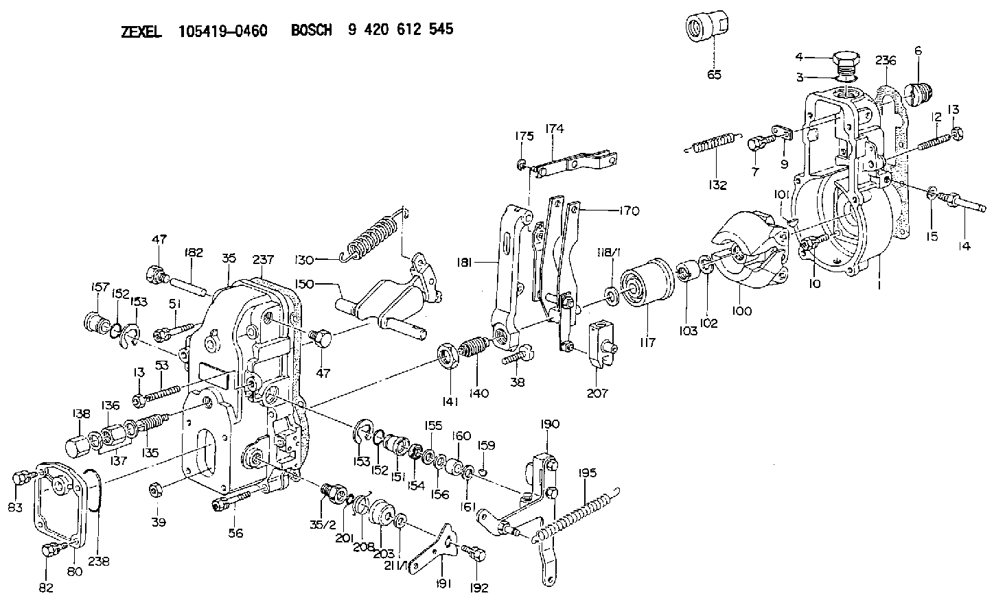
| 1. | [1] | 154000-6400 | GOVERNOR HOUSING |
| 3. | [1] | 029632-5070 | O-RING |
| 4. | [1] | 154007-2900 | CAPSULE |
| 6. | [1] | 154007-0200 | ADAPTOR |
| 7. | [1] | 020018-1840 | BLEEDER SCREW M8P1.25L18 |
| 9. | [1] | 154350-1900 | PLATE |
| 10. | [6] | 029010-6810 | BLEEDER SCREW |
| 12. | [1] | 154010-0100 | FLAT-HEAD SCREW |
| 13. | [2] | 154011-0100 | HEXAGON NUT |
| 13. | [2] | 154011-0100 | HEXAGON NUT |
| 14. | [1] | 154012-1500 | BLEEDER SCREW |
| 15. | [1] | 014110-8440 | LOCKING WASHER |
| 35. | [1] | 154500-3020 | GOVERNOR COVER |
| 35/2. | [1] | 154321-0400 | BUSHING |
| 38. | [1] | 154031-0100 | FLAT-HEAD SCREW |
| 39. | [1] | 013020-6020 | UNION NUT M6P1H5 |
| 47. | [2] | 154036-0300 | CAPSULE |
| 47. | [2] | 154036-0300 | CAPSULE |
| 51. | [2] | 020106-5040 | BLEEDER SCREW |
| 53. | [1] | 154010-0100 | FLAT-HEAD SCREW |
| 56. | [4] | 020106-3840 | BLEEDER SCREW |
| 65. | [1] | 155404-0200 | CAP |
| 80. | [1] | 154060-4900 | COVER |
| 82. | [2] | 029020-6210 | BLEEDER SCREW |
| 83. | [2] | 020006-1640 | BLEEDER SCREW M6P1L16 4T |
| 100. | [1] | 154100-9720 | FLYWEIGHT ASSEMBLY |
| 101. | [1] | 025803-1610 | WOODRUFF KEY |
| 102. | [1] | 029321-2020 | LOCKING WASHER |
| 103. | [1] | 029231-2030 | UNION NUT |
| 117. | [1] | 154123-0120 | SLIDING PIECE |
| 118/1. | [0] | 029311-0010 | SHIM D14&10.1T0.2 |
| 118/1. | [0] | 029311-0180 | SHIM D14&10.1T0.3 |
| 118/1. | [0] | 029311-0190 | SHIM D14&10.1T0.40 |
| 118/1. | [0] | 029311-0210 | SHIM D14&10.1T1 |
| 118/1. | [0] | 139410-0000 | SHIM D14.0&10.1T0.5 |
| 118/1. | [0] | 139410-0100 | SHIM D14.0&10.1T1.5 |
| 118/1. | [0] | 139410-3000 | SHIM D14&10.1T2.0 |
| 118/1. | [0] | 139410-3100 | SHIM D14&10.1T3.0 |
| 118/1. | [0] | 139410-3200 | SHIM D14&10.1T4.0 |
| 130. | [1] | 154150-2900 | GOVERNOR SPRING |
| 132. | [1] | 154154-4100 | COILED SPRING |
| 135. | [1] | 154157-5220 | HEADLESS SCREW |
| 136. | [1] | 029201-2030 | UNION NUT M12P1.0H4 |
| 137. | [2] | 026512-1540 | GASKET D15.4&12.2T1.50 |
| 138. | [1] | 154159-0100 | CAP NUT |
| 140. | [1] | 154185-1320 | HEADLESS SCREW |
| 141. | [1] | 029201-6010 | UNION NUT |
| 150. | [1] | 154200-6920 | SWIVELLING LEVER |
| 151. | [1] | 154204-3000 | BUSHING |
| 152. | [2] | 029631-8020 | O-RING |
| 152. | [2] | 029631-8020 | O-RING |
| 153. | [2] | 016010-1640 | LOCKING WASHER |
| 153. | [2] | 016010-1640 | LOCKING WASHER |
| 154. | [1] | 139611-0000 | PACKING RING |
| 155. | [1] | 139411-0000 | SHIM |
| 156. | [0] | 029311-1070 | SHIM D16&11T0.5 |
| 157. | [1] | 154204-3100 | BUSHING |
| 159. | [1] | 025803-1310 | WOODRUFF KEY |
| 160. | [1] | 154206-2800 | BUSHING |
| 161. | [0] | 154206-0200 | PLAIN WASHER D19.5&11.2T1.0 |
| 170. | [1] | 154210-0820 | FORK LEVER |
| 174. | [1] | 154230-3920 | STRAP |
| 175. | [1] | 016010-0540 | LOCKING WASHER |
| 181. | [1] | 154236-4100 | TENSIONING LEVER |
| 182. | [1] | 154237-0100 | BEARING PIN |
| 190. | [1] | 154303-5220 | CONTROL LEVER |
| 191. | [1] | 154307-0100 | CONTROL LEVER |
| 192. | [1] | 020006-1640 | BLEEDER SCREW M6P1L16 4T |
| 195. | [1] | 154314-0200 | COILED SPRING |
| 201. | [1] | 029631-0030 | O-RING &9.8W2.3 |
| 203. | [1] | 154322-0100 | CAP |
| 207. | [1] | 154326-5120 | CONTROL LEVER |
| 208. | [1] | 154327-7300 | COILED SPRING |
| 211/1. | [0] | 029311-0520 | SHIM D20.8&10.3T0.2 |
| 211/1. | [0] | 029311-0530 | SHIM D20.8&10.3T0.25 |
| 211/1. | [0] | 029311-0540 | SHIM D20.8&10.3T0.3 |
| 211/1. | [0] | 029311-0550 | SHIM D20.8&10.3T0.35 |
| 211/1. | [0] | 029311-0560 | SHIM D20.8&10.3T0.4 |
| 211/1. | [0] | 029311-0570 | SHIM D20.8&10.3T0.5 |
| 236. | [1] | 154390-0000 | GASKET |
| 237. | [1] | 154390-0300 | GASKET |
| 238. | [1] | 029635-2020 | O-RING |
Include in #1:
101342-0412
as GOVERNOR
Cross reference number
Zexel num
Bosch num
Firm num
Name
105419-0460
9813205101 ISUZU
GOVERNOR
K 14JB MECHANICAL GOVERNOR GOV RSV GOV
K 14JB MECHANICAL GOVERNOR GOV RSV GOV
Information:
Charging System
The condition of charge in the battery at each regular inspection will show if the charging system operates correctly. An adjustment is necessary when the battery is constantly in a low condition of charge or a large amount of water is needed (more than one ounce of water per cell per week or per every 100 service hours).When it is possible, make a test of the charging unit and voltage regulator on the engine, and use wiring and components that are a permanent part of the system. Off-engine (bench) testing will give a test of the charging unit and voltage regulator operation. This testing will give an indication of needed repair. After repairs are made, again make a test to give proof that the units are repaired to their original condition of operation.Before the start of on-engine testing, the charging system and battery must be checked as shown in the Steps that follow:1. Battery must be at least 75% (1.225 Sp. Gr.) fully charged and held tightly in place. The battery holder must not put too much stress on the battery.2. Cables between the battery, starter and engine ground must be the correct size. Wires and cables must be free of corrosion and have cable support clamps to prevent stress on battery connections (terminals).3. Leads, junctions, switches and panel instruments that have direct relation to the charging circuit must give correct circuit control.4. Inspect the drive components for the charging unit to be sure they are free of grease and oil and have the ability to operate the charging unit.Delco-Remy Alternator; Pulley Nut Tightening
Tighten nut that holds the pulley to a torque of 100 7 N m (75 5 lb ft) with the tools shown.
Tools To Tighten Alternator Pulley Nut
(1) 8T9293 Torque Wrench. (2) 8S1588 Adapter (1/2" female to 3/8" male). (3) 2P8267 Socket Assembly. (4) 8H8517 Combination Wrench (1 1/8"). (5) 8T5314 Socket.Alternator Regulator Adjustment - (Delco-Remy)
When an alternator is charging the battery too much or not enough, an adjustment can be made to the charging rate of the alternator. Make reference to the Specifications section to find all testing specifications for the alternators and regulators.3T6352 Alternator 24V 35A (Delco-Remy Number 1117647)
3T6352 AlternatorNo adjustment can be made to change the rate of charge on the alternator regulator. If rate of charge is not correct, a replacement of the regulator is necessary.7N9720 Alternator 24V 35A (Bosch Number 0-122-469-001)
7N9720 AlternatorThe solid state regulator used with the Bosch Alternator is totally enclosed and non-adjustable. If the rate of charge is not correct a replacement of the regulator is necessary.9G4574 24V 35A (Nippondenso Number 100211-0860)
9G4574 AlternatorNo adjustment can be made to change the rate of charge on the alternator regulator. If rate of charge is not correct, a replacement of the regulator is necessary.Starting System
Use the multimeter in the DCV range to find starting system components which do not function.Move the start control switch to activate the starter solenoid. Starter solenoid operation can be heard as the pinion