Information governor
BOSCH
9 420 612 784
9420612784
ZEXEL
105419-0230
1054190230
ISUZU
8943864460
8943864460
Rating:
Scheme ###:
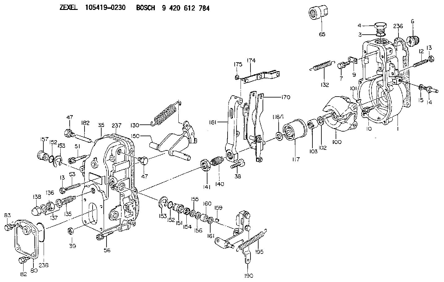
| 1. | [1] | 154000-6400 | GOVERNOR HOUSING |
| 3. | [1] | 029632-5070 | O-RING |
| 4. | [1] | 154007-2900 | CAPSULE |
| 6. | [1] | 154007-0200 | ADAPTOR |
| 7. | [1] | 020018-1840 | BLEEDER SCREW M8P1.25L18 |
| 9. | [1] | 154350-1900 | PLATE |
| 10. | [6] | 029010-6810 | BLEEDER SCREW |
| 12. | [1] | 154010-1100 | FLAT-HEAD SCREW |
| 13. | [2] | 154011-0100 | HEXAGON NUT |
| 13. | [2] | 154011-0100 | HEXAGON NUT |
| 14. | [1] | 154012-1500 | BLEEDER SCREW |
| 15. | [1] | 014110-8440 | LOCKING WASHER |
| 35. | [1] | 154500-2020 | GOVERNOR COVER |
| 38. | [1] | 154031-0100 | FLAT-HEAD SCREW |
| 39. | [1] | 013020-6020 | UNION NUT M6P1H5 |
| 47. | [2] | 154036-0300 | CAPSULE |
| 47. | [2] | 154036-0300 | CAPSULE |
| 51. | [2] | 020106-5040 | BLEEDER SCREW |
| 53. | [1] | 154010-0100 | FLAT-HEAD SCREW |
| 56. | [4] | 020106-3840 | BLEEDER SCREW |
| 65. | [1] | 154050-1720 | STOPPING DEVICE |
| 80. | [1] | 154060-4900 | COVER |
| 82. | [2] | 029020-6210 | BLEEDER SCREW |
| 83. | [2] | 020006-1640 | BLEEDER SCREW M6P1L16 4T |
| 100. | [1] | 154101-0120 | FLYWEIGHT |
| 101. | [1] | 025803-1610 | WOODRUFF KEY |
| 102. | [1] | 029321-2020 | LOCKING WASHER |
| 103. | [1] | 029231-2030 | UNION NUT |
| 117. | [1] | 154123-0120 | SLIDING PIECE |
| 118/1. | [0] | 029311-0010 | SHIM D14&10.1T0.2 |
| 118/1. | [0] | 029311-0180 | SHIM D14&10.1T0.3 |
| 118/1. | [0] | 029311-0190 | SHIM D14&10.1T0.40 |
| 118/1. | [0] | 029311-0210 | SHIM D14&10.1T1 |
| 118/1. | [0] | 139410-0000 | SHIM D14.0&10.1T0.5 |
| 118/1. | [0] | 139410-0100 | SHIM D14.0&10.1T1.5 |
| 118/1. | [0] | 139410-3000 | SHIM D14&10.1T2.0 |
| 118/1. | [0] | 139410-3100 | SHIM D14&10.1T3.0 |
| 118/1. | [0] | 139410-3200 | SHIM D14&10.1T4.0 |
| 130. | [1] | 154150-6400 | GOVERNOR SPRING |
| 132. | [1] | 154154-1200 | COILED SPRING |
| 135. | [1] | 154157-1620 | HEADLESS SCREW |
| 136. | [1] | 029201-2130 | UNION NUT M12P1.0H6 |
| 137. | [2] | 026512-1540 | GASKET D15.4&12.2T1.50 |
| 138. | [1] | 154159-0100 | CAP NUT |
| 140. | [1] | 154170-6820 | HEADLESS SCREW |
| 141. | [1] | 029201-6010 | UNION NUT |
| 150. | [1] | 154200-6920 | SWIVELLING LEVER |
| 151. | [1] | 154204-3000 | BUSHING |
| 152. | [2] | 029631-8020 | O-RING |
| 152. | [2] | 029631-8020 | O-RING |
| 153. | [2] | 016010-1640 | LOCKING WASHER |
| 153. | [2] | 016010-1640 | LOCKING WASHER |
| 154. | [1] | 139611-0000 | PACKING RING |
| 155. | [1] | 139411-0000 | SHIM |
| 156. | [0] | 029311-1090 | SHIM D16&11T0.3 |
| 157. | [1] | 154204-3100 | BUSHING |
| 159. | [1] | 025803-1310 | WOODRUFF KEY |
| 160. | [1] | 154206-2800 | BUSHING |
| 161. | [0] | 154206-0200 | PLAIN WASHER D19.5&11.2T1.0 |
| 170. | [1] | 154211-3820 | FORK LEVER |
| 174. | [1] | 154230-0120 | STRAP |
| 175. | [1] | 016010-0540 | LOCKING WASHER |
| 181. | [1] | 154236-4100 | TENSIONING LEVER |
| 182. | [1] | 154237-0100 | BEARING PIN |
| 190. | [1] | 154303-5220 | CONTROL LEVER |
| 195. | [1] | 154314-0200 | COILED SPRING |
| 236. | [1] | 154390-0000 | GASKET |
| 237. | [1] | 154390-0300 | GASKET |
| 238. | [1] | 029635-2020 | O-RING |
Cross reference number
Zexel num
Bosch num
Firm num
Name
Information:
START BY:a. remove valve coversb. remove rocker shaft assemblies and pushrodsc. remove fuel injection nozzles (earlier)
Be sure that the piston is at Top Center so that the valves will be held in position when the springs are removed.
1. Remove the valve cover bases.2. Remove the valve stem locks with tooling (A) using the following procedure: a. Install adapter plate (1) with two OS1618 (5/16-18 x 1 in.) bolts.b. Install stud (2) and nut (3). Tighten the nut. c. Install plate (4), washer (5) and nut (6). Tighten the nut until the locks are free.d. Remove locks (7), and remove the nut, washer and plate from the stud. Remove the stud and adapter plate from the fuel injection nozzle adapter. 3. Remove rotocoil (8), spring (9) and washer (10). 4. Use tool (B) to remove fuel injection nozzle adapter (11) from the cylinder head assembly. 5. Remove washers (12) and seals (13) from adapters (11).Install Fuel Injection Nozzle Adapters (Earlier)
1. Inspect seals (3) for damage or wear, and make a replacement if necessary.2. Install washers (1) and seals (3) on adapters (2).3. Put liquid soap in the bores of the cylinder head and on the seals of the fuel injection nozzle adapters.4. Put 5P3931 Anti-Seize Compound on the threads of adapter (2), and install the adapters in the cylinder head assembly. 5. Use tool (A), and tighten the adapters to a torque of 205 14 N m (150 10 lb.ft.). 6. Install washers (6), springs (5) and rotocoils (4). 7. Use tool (B), and compress the springs until locks (7) can be installed. Install locks (7) on the valve stems, and remove tool (B).8. Install the valve cover base. Tighten the valve cover base mounting bolts to a torque of 14 3 N m (10 2 lb.ft.).END BY:a. install fuel injection nozzles (earlier)b. install rocker shaft assemblies and push rodsc. install valve covers