Information governor
BOSCH
9 420 614 226
9420614226
ZEXEL
105412-1980
1054121980
Rating:
Scheme ###:
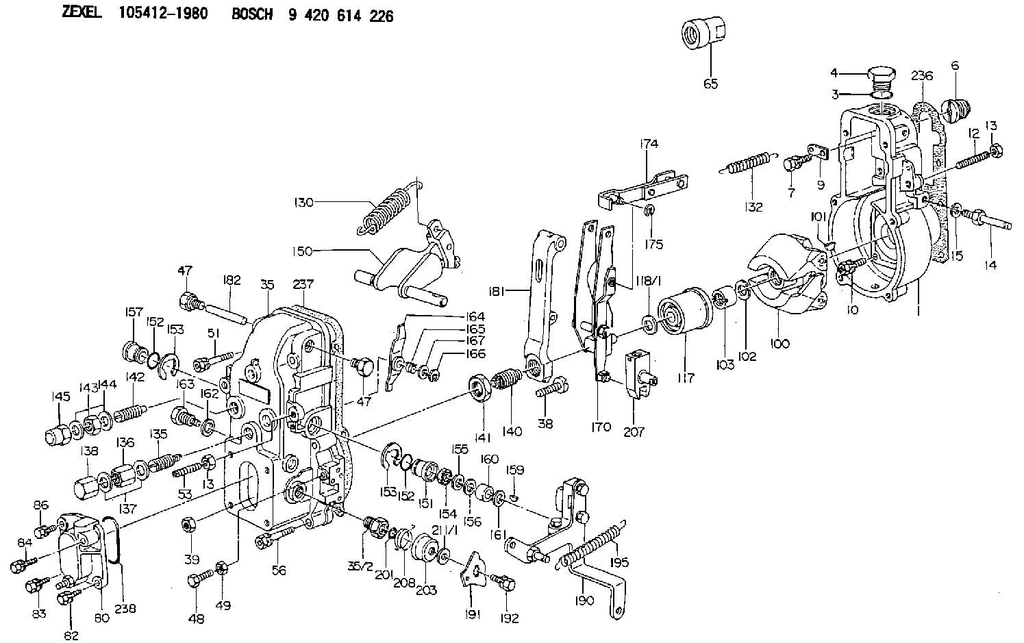
| 1. | [1] | 154000-6400 | GOVERNOR HOUSING |
| 3. | [1] | 029632-5070 | O-RING |
| 4. | [1] | 154007-2900 | CAPSULE |
| 6. | [1] | 154007-0200 | ADAPTOR |
| 7. | [1] | 020018-1840 | BLEEDER SCREW M8P1.25L18 |
| 9. | [1] | 154350-1900 | PLATE |
| 10. | [6] | 029010-6810 | BLEEDER SCREW |
| 12. | [1] | 154010-0100 | FLAT-HEAD SCREW |
| 13. | [2] | 154011-0100 | HEXAGON NUT |
| 13. | [2] | 154011-0100 | HEXAGON NUT |
| 14. | [1] | 154012-1500 | BLEEDER SCREW |
| 15. | [1] | 014110-8440 | LOCKING WASHER |
| 35. | [1] | 154500-3120 | GOVERNOR COVER |
| 35/2. | [1] | 154321-0400 | BUSHING |
| 38. | [1] | 154031-0100 | FLAT-HEAD SCREW |
| 39. | [1] | 013020-6020 | UNION NUT M6P1H5 |
| 47. | [2] | 154036-0300 | CAPSULE |
| 47. | [2] | 154036-0300 | CAPSULE |
| 48. | [1] | 154037-0700 | BLEEDER SCREW |
| 49. | [1] | 154038-0200 | HEXAGON NUT |
| 51. | [2] | 020106-5040 | BLEEDER SCREW |
| 53. | [1] | 154010-0200 | FLAT-HEAD SCREW |
| 56. | [4] | 020106-3840 | BLEEDER SCREW |
| 65. | [1] | 155404-0200 | CAP |
| 80. | [1] | 154060-1020 | COVER |
| 82. | [1] | 029020-6210 | BLEEDER SCREW |
| 83. | [1] | 029020-6210 | BLEEDER SCREW |
| 84. | [1] | 029000-6800 | BLEEDER SCREW |
| 86. | [1] | 020006-1640 | BLEEDER SCREW M6P1L16 4T |
| 100. | [1] | 154100-3220 | FLYWEIGHT ASSEMBLY |
| 101. | [1] | 025803-1610 | WOODRUFF KEY |
| 102. | [1] | 029321-2020 | LOCKING WASHER |
| 103. | [1] | 029231-2030 | UNION NUT |
| 117. | [1] | 154123-0120 | SLIDING PIECE |
| 118/1. | [0] | 029311-0010 | SHIM D14&10.1T0.2 |
| 118/1. | [0] | 029311-0180 | SHIM D14&10.1T0.3 |
| 118/1. | [0] | 029311-0190 | SHIM D14&10.1T0.40 |
| 118/1. | [0] | 029311-0210 | SHIM D14&10.1T1 |
| 118/1. | [0] | 139410-0000 | SHIM D14.0&10.1T0.5 |
| 118/1. | [0] | 139410-0100 | SHIM D14.0&10.1T1.5 |
| 118/1. | [0] | 139410-3000 | SHIM D14&10.1T2.0 |
| 118/1. | [0] | 139410-3100 | SHIM D14&10.1T3.0 |
| 118/1. | [0] | 139410-3200 | SHIM D14&10.1T4.0 |
| 130. | [1] | 154150-0400 | GOVERNOR SPRING |
| 132. | [1] | 154154-0800 | COILED SPRING |
| 135. | [1] | 154157-0120 | HEADLESS SCREW |
| 136. | [1] | 029201-2030 | UNION NUT M12P1.0H4 |
| 137. | [2] | 026512-1540 | GASKET D15.4&12.2T1.50 |
| 138. | [1] | 154159-1200 | CAP NUT |
| 140. | [1] | 154178-7520 | HEADLESS SCREW |
| 141. | [1] | 029201-6010 | UNION NUT |
| 142. | [1] | 154242-0420 | HEADLESS SCREW |
| 143. | [1] | 029201-6150 | UNION NUT |
| 144. | [2] | 026516-2040 | GASKET D19.9&16.2T1 |
| 145. | [1] | 154159-1100 | CAP NUT |
| 150. | [1] | 154200-0120 | SWIVELLING LEVER |
| 151. | [2] | 154204-1900 | BUSHING |
| 152. | [2] | 029631-8020 | O-RING |
| 152. | [2] | 029631-8020 | O-RING |
| 153. | [2] | 016010-1640 | LOCKING WASHER |
| 153. | [2] | 016010-1640 | LOCKING WASHER |
| 154. | [1] | 139611-0000 | PACKING RING |
| 155. | [1] | 139411-0000 | SHIM |
| 156. | [0] | 029311-1090 | SHIM D16&11T0.3 |
| 157. | [1] | 029141-7010 | CAPSULE |
| 159. | [1] | 025803-1310 | WOODRUFF KEY |
| 160. | [1] | 154206-2800 | BUSHING |
| 161. | [0] | 154206-0200 | PLAIN WASHER D19.5&11.2T1.0 |
| 162. | [1] | 029331-0240 | GASKET |
| 163. | [1] | 154401-2700 | BLEEDER SCREW |
| 164. | [1] | 154243-0220 | CONTROL LEVER |
| 165. | [1] | 154327-1900 | COILED SPRING |
| 166. | [1] | 016010-0710 | LOCKING WASHER |
| 167. | [1] | 029310-8020 | PLAIN WASHER D15&8.4T0.3 |
| 170. | [1] | 154211-0120 | FORK LEVER |
| 174. | [1] | 154230-3920 | STRAP |
| 175. | [1] | 016010-0540 | LOCKING WASHER |
| 181. | [1] | 154236-3220 | TENSIONING LEVER |
| 182. | [1] | 154237-0100 | BEARING PIN |
| 190. | [1] | 154342-1420 | CONTROL LEVER |
| 191. | [1] | 154308-4100 | CONTROL LEVER |
| 192. | [1] | 020006-1640 | BLEEDER SCREW M6P1L16 4T |
| 195. | [1] | 154314-0200 | COILED SPRING |
| 201. | [1] | 029631-0030 | O-RING &9.8W2.3 |
| 203. | [1] | 154322-0100 | CAP |
| 207. | [1] | 154326-5820 | CONTROL LEVER |
| 208. | [1] | 154327-7300 | COILED SPRING |
| 211/1. | [0] | 029311-0520 | SHIM D20.8&10.3T0.2 |
| 211/1. | [0] | 029311-0530 | SHIM D20.8&10.3T0.25 |
| 211/1. | [0] | 029311-0540 | SHIM D20.8&10.3T0.3 |
| 211/1. | [0] | 029311-0550 | SHIM D20.8&10.3T0.35 |
| 211/1. | [0] | 029311-0560 | SHIM D20.8&10.3T0.4 |
| 211/1. | [0] | 029311-0570 | SHIM D20.8&10.3T0.5 |
| 236. | [1] | 154390-0000 | GASKET |
| 237. | [1] | 154390-0300 | GASKET |
| 238. | [1] | 029635-2020 | O-RING |
Include in #1:
101602-9430
as GOVERNOR
Cross reference number
Zexel num
Bosch num
Firm num
Name
Information:
(1) Diameter of the surfaces (journals) for the camshaft bearings (new) ... 63.500 0.013 mm (2.5000 .0005 in) Bore in the five bearings for the camshaft (new) ... 63.589 0.038 mm (2.5035 .0015 in)Maximum permissible clearance between bearing and bearing surface (journal) (worn) ... 0.18 mm (.007 in)(2) Tight fit between the gear and camshaft ... 0.030 to 0.071 mm (.0012 to .0028 in) Maximum permissible temperature of the gear for installation on the camshaft (do not use a torch) ... 315°C (600°F)(3) End play for the camshaft ... 0.18 0.08 mm (.007 .003 in) Maximum permissible end play (worn) ... 0.51 mm (.020 in)(4) Width of thrust groove in camshaft (new) ... 9.14 0.05 mm (.360 .002 in) Diameter of thrust pin (new) ... 8.97 0.03 mm (.353 .001 in)Torque for thrust pin ... 48 7 N m (35 5 lb ft)(5) Height of camshaft lobes.To find lobe lift, use the procedure that follows:A. Measure camshaft lobe height (5).B. Measure base circle (7).C. Subtract base circle (Step B) from lobe height (Step A). The difference is actual lobe lift (6).D. Specified camshaft lobe lift (6) is: 9N5230 Camshaft used with roller lifters: a. Exhaust lobe ... 9.40 mm (.370 in) b. Intake lobe ... 9.33 mm (.367 in)2W4238 Camshaft used with flat face lifters: c. Exhaust lobe ... 9.40 mm (.370 in) d. Intake lobe ... 9.06 mm (.357 in)Maximum permissible difference between actual lobe lift (Step C) and specified lobe lift (Step D) is 0.25 mm (.010 in).
Camshaft Gear Assembly
View A-A(8) Distance from the end of 9N5771 Dowell to the face of gear ... 11.81 0.13 mm(.465 .005 in)
View B-B(9) Distance from the end of 5P4283 Dowel to the face of camshaft ... 2.00 0.25 mm(.079 .010 in)Camshaft Installation
For installation of camshaft, the timing mark on the camshaft gear tooth must be in alignment with the timing mark on the tooth space of the crankshaft gear.Intake Valve Timing
1. Check the No. 1 intake valve clearance with the engine stopped. The valve clearance must be 0.30 to 0.46 mm (.012 to .018 in). If the valve clearance is not in this range, adjust the clearance to 0.38 mm (.015 in).2. Mark Top Center Position of the crankshaft on the vibration damper or pulley.3. Use a dial indicator to measure the intake valve movement.4. Rotate the crankshaft in the direction of normal engine rotation. Stop when the intake valve is 1.91 mm (.075 in) off its seat in the opening sequence. At this point the crankshaft must be 10 2° After Top Center.