Information governor
BOSCH
F 019 Z1E 402
f019z1e402
ZEXEL
105412-1810
1054121810
MITSUBISHI
ME059515
me059515
Rating:
Scheme ###:
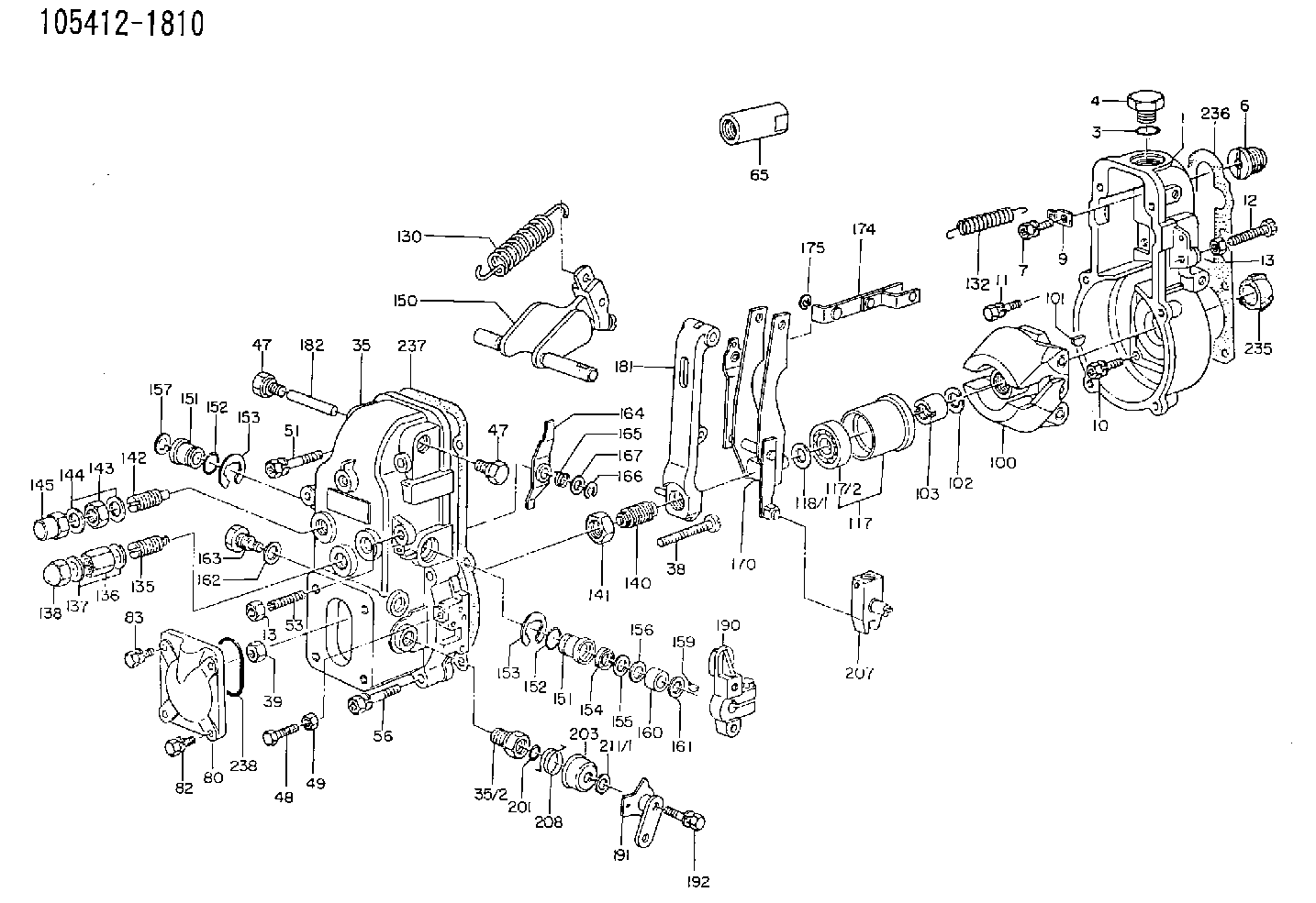
| 1. | [1] | 154000-7000 | GOVERNOR HOUSING |
| 3. | [1] | 029632-5070 | O-RING |
| 4. | [1] | 154007-2900 | CAPSULE |
| 6. | [1] | 154007-0200 | ADAPTOR |
| 7. | [1] | 020018-1840 | BLEEDER SCREW M8P1.25L18 |
| 9. | [1] | 154350-1900 | PLATE |
| 10. | [5] | 029010-6810 | BLEEDER SCREW |
| 11. | [1] | 020106-1640 | BLEEDER SCREW M6P1.0L14 |
| 12. | [1] | 154010-1100 | FLAT-HEAD SCREW |
| 13. | [2] | 154011-0100 | HEXAGON NUT |
| 13. | [2] | 154011-0100 | HEXAGON NUT |
| 35. | [1] | 154500-3120 | GOVERNOR COVER |
| 35/2. | [1] | 154321-0400 | BUSHING |
| 38. | [1] | 154031-0100 | FLAT-HEAD SCREW |
| 39. | [1] | 013020-6020 | UNION NUT M6P1H5 |
| 47. | [2] | 154036-0300 | CAPSULE |
| 47. | [2] | 154036-0300 | CAPSULE |
| 48. | [1] | 154037-0700 | BLEEDER SCREW |
| 49. | [1] | 154038-0200 | HEXAGON NUT |
| 51. | [2] | 020106-5040 | BLEEDER SCREW |
| 53. | [1] | 154010-0100 | FLAT-HEAD SCREW |
| 56. | [4] | 020106-3840 | BLEEDER SCREW |
| 65. | [1] | 155404-3700 | CAP |
| 80. | [1] | 154060-3800 | COVER |
| 82. | [2] | 029020-6210 | BLEEDER SCREW |
| 83. | [2] | 020006-1640 | BLEEDER SCREW M6P1L16 4T |
| 100. | [1] | 154100-2320 | FLYWEIGHT ASSEMBLY |
| 101. | [1] | 025803-1610 | WOODRUFF KEY |
| 102. | [1] | 029321-2020 | LOCKING WASHER |
| 103. | [1] | 029231-2030 | UNION NUT |
| 117. | [1] | 154123-0120 | SLIDING PIECE |
| 118/1. | [0] | 029311-0010 | SHIM D14&10.1T0.2 |
| 118/1. | [0] | 029311-0180 | SHIM D14&10.1T0.3 |
| 118/1. | [0] | 029311-0190 | SHIM D14&10.1T0.40 |
| 118/1. | [0] | 029311-0210 | SHIM D14&10.1T1 |
| 118/1. | [0] | 139410-0000 | SHIM D14.0&10.1T0.5 |
| 118/1. | [0] | 139410-0100 | SHIM D14.0&10.1T1.5 |
| 118/1. | [0] | 139410-3000 | SHIM D14&10.1T2.0 |
| 118/1. | [0] | 139410-3100 | SHIM D14&10.1T3.0 |
| 118/1. | [0] | 139410-3200 | SHIM D14&10.1T4.0 |
| 130. | [1] | 154150-2900 | GOVERNOR SPRING |
| 132. | [1] | 154154-0400 | COILED SPRING |
| 135. | [1] | 154157-1620 | HEADLESS SCREW |
| 136. | [1] | 029201-2030 | UNION NUT M12P1.0H4 |
| 137. | [2] | 026512-1540 | GASKET D15.4&12.2T1.50 |
| 138. | [1] | 154159-0100 | CAP NUT |
| 140. | [1] | 154185-1320 | HEADLESS SCREW |
| 141. | [1] | 029201-6010 | UNION NUT |
| 142. | [1] | 154242-0420 | HEADLESS SCREW |
| 143. | [1] | 029201-6150 | UNION NUT |
| 144. | [2] | 026516-2040 | GASKET D19.9&16.2T1 |
| 145. | [1] | 154159-1100 | CAP NUT |
| 150. | [1] | 154200-6920 | SWIVELLING LEVER |
| 151. | [1] | 154204-4300 | BUSHING |
| 151. | [1] | 154204-4300 | BUSHING |
| 152. | [2] | 029631-8020 | O-RING |
| 152. | [2] | 029631-8020 | O-RING |
| 153. | [2] | 016010-1640 | LOCKING WASHER |
| 153. | [2] | 016010-1640 | LOCKING WASHER |
| 154. | [1] | 139611-0000 | PACKING RING |
| 155. | [1] | 139411-0000 | SHIM |
| 156. | [0] | 029311-1070 | SHIM D16&11T0.5 |
| 157. | [1] | 154204-4400 | BUSHING |
| 159. | [1] | 025803-1310 | WOODRUFF KEY |
| 160. | [1] | 154206-2800 | BUSHING |
| 161. | [0] | 154206-0200 | PLAIN WASHER D19.5&11.2T1.0 |
| 162. | [1] | 029331-0240 | GASKET |
| 163. | [1] | 154401-2700 | BLEEDER SCREW |
| 164. | [1] | 154243-0220 | CONTROL LEVER |
| 165. | [1] | 154327-1900 | COILED SPRING |
| 166. | [1] | 016010-0710 | LOCKING WASHER |
| 167. | [1] | 029310-8020 | PLAIN WASHER D15&8.4T0.3 |
| 170. | [1] | 154217-4820 | FORK LEVER |
| 174. | [1] | 154230-3920 | STRAP |
| 175. | [1] | 016010-0540 | LOCKING WASHER |
| 181. | [1] | 154236-3220 | TENSIONING LEVER |
| 182. | [1] | 154237-0100 | BEARING PIN |
| 190. | [1] | 154340-0120 | CONTROL LEVER |
| 191. | [1] | 154364-3420 | CONTROL LEVER |
| 192. | [1] | 020006-4540 | BLEEDER SCREW M6P1L45 |
| 201. | [1] | 029631-0030 | O-RING &9.8W2.3 |
| 203. | [1] | 154322-0100 | CAP |
| 207. | [1] | 154326-9020 | LEVER GROUP |
| 208. | [1] | 154327-7300 | COILED SPRING |
| 211/1. | [0] | 029311-0520 | SHIM D20.8&10.3T0.2 |
| 211/1. | [0] | 029311-0530 | SHIM D20.8&10.3T0.25 |
| 211/1. | [0] | 029311-0540 | SHIM D20.8&10.3T0.3 |
| 211/1. | [0] | 029311-0550 | SHIM D20.8&10.3T0.35 |
| 211/1. | [0] | 029311-0560 | SHIM D20.8&10.3T0.4 |
| 211/1. | [0] | 029311-0570 | SHIM D20.8&10.3T0.5 |
| 236. | [1] | 154390-1300 | GASKET |
| 237. | [1] | 154390-0300 | GASKET |
| 238. | [1] | 029635-5010 | O-RING |
Include in #1:
101601-6950
as GOVERNOR
Cross reference number
Zexel num
Bosch num
Firm num
Name
105412-1810
ME059515 MITSUBISHI
GOVERNOR
K 14JB MECHANICAL GOVERNOR GOV RSV GOV
K 14JB MECHANICAL GOVERNOR GOV RSV GOV
Information:
1. Disconnect the glow plug wires and crankcase ventilation tube. Remove the valve cover. 2. Remove the No. 1 fuel injection line (1) and fuel injection valve (2). 3. Install the adapter (3), rod (4), and dial indicator (5) from tool group (A) in the precombustion chamber.
Tighten adapter (4) finger tight only to prevent damage to the fuel valve seat.
4. Rotate the crankshaft in the direction of engine rotation (counterclockwise as viewed the flywheel end) until the maximum reading is read on the dial indicator and the No. 1 cylinder intake and exhaust valves (6) are both closed. The glow plugs can be removed to ease turning of the crankshaft.5. Zero the dial indicator by moving the indicator up or down in the adapter to position the small hand between the red zero and the black zero. Turn the face of the indicator to align the zero with the large hand. Rotate the crankshaft in reverse rotation approximately 30° and repeat step 4 to verify that dial indicator is properly zeroed. 6. Using the rod (9) and plug (8) from tool group (A), depress the oil pressure speed limiter plunger. Move the governor control arm to the full fuel on position and hold it in that position with wire (7). 7. Install the tube assembly (10) from tool group (B), on No. 1 fuel injection pump and slant it slightly upward. Position a suitable container under the tube to catch fuel. 8. Connect the tank hose (12) to the accessory drive housing as shown.9. Fill the tank with a gallon of clean fuel and pressurize it to 15 psi (1,05 kg/cm2) by using the hand pump. If available shop air can be used to pressurize the tank with the use of a pressure regulator (11).
When using shop air adjust the pressure regulator to 15 psi (1,05 kg/cm2) before connecting hose (12) to the engine.
10. Rotate the crankshaft in reverse rotation approximately 30° from TDC (top dead center). At this point a solid stream of fuel should be coming out of the tube.11. Rotate the crankshaft slowly in normal direction of rotation until the fuel flow from the tube is reduced to 6 to 12 drops per minute. At this point the fuel injection pump plunger closes the bypass port and fuel injection begins.12. The reading on the dial indicator, using the red numbers, should be .109 in. BTC (before top center) which is equal to 13.5° fuel injection pump timing. If the reading is not obtained retiming is required. The chart below converts inches of piston travel into degrees of crankshaft rotation. 13. If the engine is properly timed, remove the timing tools and install the valve cover (see INSTALL VALVE COVER for tightening sequence of the bolts), fuel injection valve and line. Tighten the fuel valve retaining nut to 105 5 lb.ft. (14,5 0,5 mkg). Tighten the fuel line nuts to 30 5 lb. ft. (4,1 0,7 mkg). If engine timing is incorrect