Information governor
BOSCH
9 420 610 036
9420610036
ZEXEL
105412-1640
1054121640
MITSUBISHI
3096190600
3096190600

Rating:
Scheme ###:
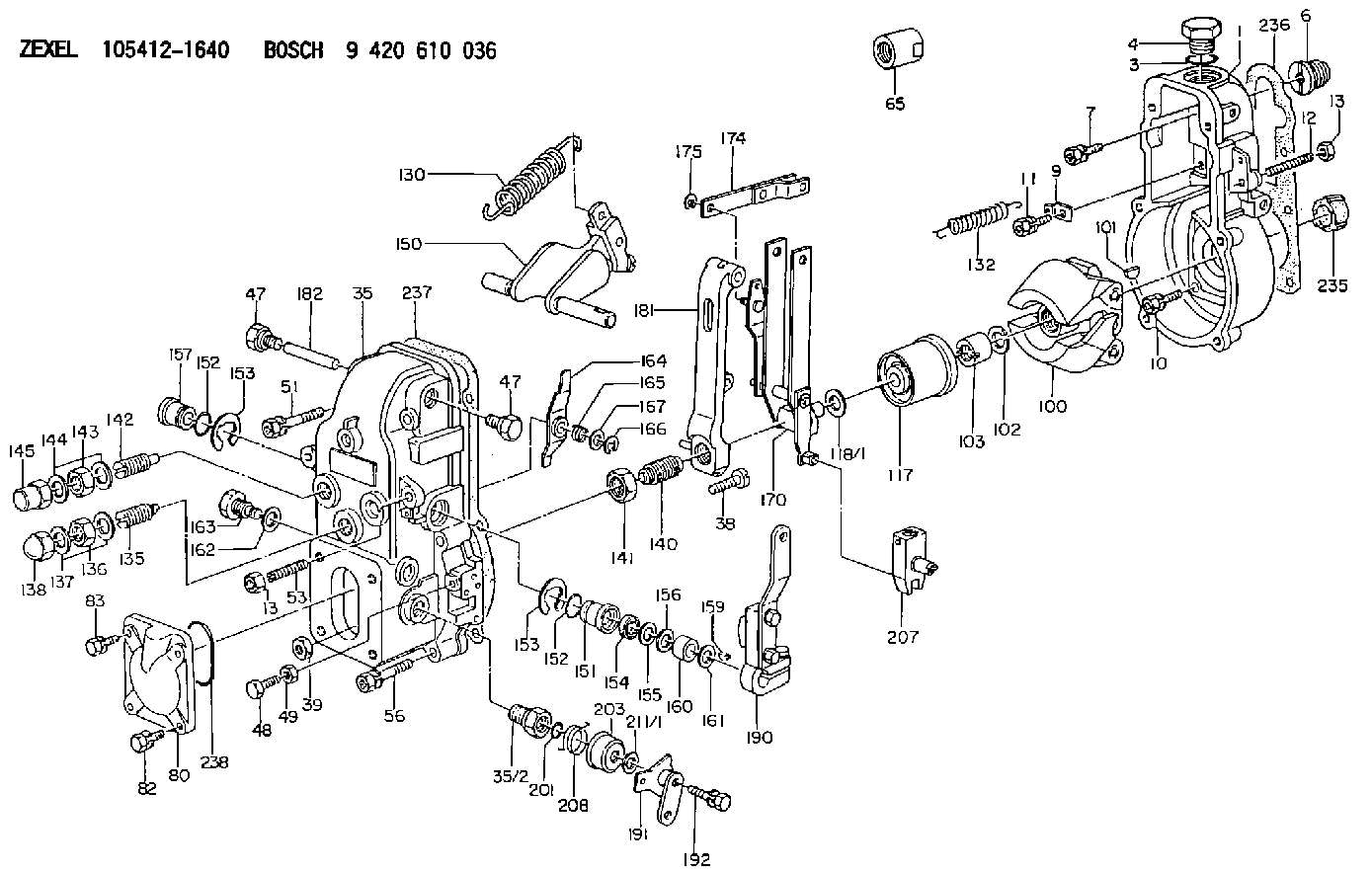
| 1. | [1] | 154000-7000 | GOVERNOR HOUSING |
| 3. | [1] | 029632-5070 | O-RING |
| 4. | [1] | 154007-2900 | CAPSULE |
| 6. | [1] | 154007-0200 | ADAPTOR |
| 7. | [1] | 020018-1840 | BLEEDER SCREW M8P1.25L18 |
| 9. | [1] | 154350-1900 | PLATE |
| 10. | [5] | 029010-6810 | BLEEDER SCREW |
| 11. | [1] | 020106-1640 | BLEEDER SCREW M6P1.0L14 |
| 12. | [1] | 154010-1100 | FLAT-HEAD SCREW |
| 13. | [2] | 154011-0100 | HEXAGON NUT |
| 13. | [2] | 154011-0100 | HEXAGON NUT |
| 35. | [1] | 154500-3120 | GOVERNOR COVER |
| 35/2. | [1] | 154321-0400 | BUSHING |
| 38. | [1] | 154031-0100 | FLAT-HEAD SCREW |
| 39. | [1] | 013020-6020 | UNION NUT M6P1H5 |
| 47. | [2] | 154036-0300 | CAPSULE |
| 47. | [2] | 154036-0300 | CAPSULE |
| 48. | [1] | 154037-0700 | BLEEDER SCREW |
| 49. | [1] | 154038-0200 | HEXAGON NUT |
| 51. | [2] | 020106-5040 | BLEEDER SCREW |
| 53. | [1] | 154010-0100 | FLAT-HEAD SCREW |
| 56. | [4] | 020106-3840 | BLEEDER SCREW |
| 65. | [1] | 155404-5700 | CAP |
| 80. | [1] | 154060-3800 | COVER |
| 82. | [2] | 029020-6210 | BLEEDER SCREW |
| 83. | [2] | 020006-1640 | BLEEDER SCREW M6P1L16 4T |
| 100. | [1] | 154100-2320 | FLYWEIGHT ASSEMBLY |
| 101. | [1] | 025803-1610 | WOODRUFF KEY |
| 102. | [1] | 029321-2020 | LOCKING WASHER |
| 103. | [1] | 029231-2030 | UNION NUT |
| 117. | [1] | 154123-0120 | SLIDING PIECE |
| 118/1. | [0] | 029311-0010 | SHIM D14&10.1T0.2 |
| 118/1. | [0] | 029311-0180 | SHIM D14&10.1T0.3 |
| 118/1. | [0] | 029311-0190 | SHIM D14&10.1T0.40 |
| 118/1. | [0] | 029311-0210 | SHIM D14&10.1T1 |
| 118/1. | [0] | 139410-0000 | SHIM D14.0&10.1T0.5 |
| 118/1. | [0] | 139410-0100 | SHIM D14.0&10.1T1.5 |
| 118/1. | [0] | 139410-3000 | SHIM D14&10.1T2.0 |
| 118/1. | [0] | 139410-3100 | SHIM D14&10.1T3.0 |
| 118/1. | [0] | 139410-3200 | SHIM D14&10.1T4.0 |
| 130. | [1] | 154150-0400 | GOVERNOR SPRING |
| 132. | [1] | 154154-0400 | COILED SPRING |
| 135. | [1] | 154157-1620 | HEADLESS SCREW |
| 136. | [1] | 029201-2030 | UNION NUT M12P1.0H4 |
| 137. | [2] | 026512-1540 | GASKET D15.4&12.2T1.50 |
| 138. | [1] | 154159-0100 | CAP NUT |
| 140. | [1] | 154176-8020 | HEADLESS SCREW |
| 141. | [1] | 029201-6010 | UNION NUT |
| 142. | [1] | 154242-1220 | HEADLESS SCREW |
| 143. | [1] | 029201-6150 | UNION NUT |
| 144. | [2] | 026516-2040 | GASKET D19.9&16.2T1 |
| 145. | [1] | 154159-1100 | CAP NUT |
| 150. | [1] | 154200-6920 | SWIVELLING LEVER |
| 151. | [1] | 154204-3000 | BUSHING |
| 152. | [2] | 029631-8020 | O-RING |
| 152. | [2] | 029631-8020 | O-RING |
| 153. | [2] | 016010-1640 | LOCKING WASHER |
| 153. | [2] | 016010-1640 | LOCKING WASHER |
| 154. | [1] | 139611-0000 | PACKING RING |
| 155. | [1] | 139411-0000 | SHIM |
| 156. | [0] | 029311-1070 | SHIM D16&11T0.5 |
| 157. | [1] | 154204-3100 | BUSHING |
| 159. | [1] | 025803-1310 | WOODRUFF KEY |
| 160. | [1] | 154206-2800 | BUSHING |
| 161. | [0] | 154206-0200 | PLAIN WASHER D19.5&11.2T1.0 |
| 162. | [1] | 029331-0240 | GASKET |
| 163. | [1] | 154401-2700 | BLEEDER SCREW |
| 164. | [1] | 154243-0220 | CONTROL LEVER |
| 165. | [1] | 154327-1900 | COILED SPRING |
| 166. | [1] | 016010-0710 | LOCKING WASHER |
| 167. | [1] | 029310-8020 | PLAIN WASHER D15&8.4T0.3 |
| 170. | [1] | 154217-4820 | FORK LEVER |
| 174. | [1] | 154230-3920 | STRAP |
| 175. | [1] | 016010-0540 | LOCKING WASHER |
| 181. | [1] | 154236-3220 | TENSIONING LEVER |
| 182. | [1] | 154237-0100 | BEARING PIN |
| 190. | [1] | 154340-0020 | CONTROL LEVER |
| 191. | [1] | 154308-4020 | CONTROL LEVER |
| 192. | [1] | 020006-3240 | BLEEDER SCREW |
| 201. | [1] | 029631-0030 | O-RING &9.8W2.3 |
| 203. | [1] | 154322-0100 | CAP |
| 207. | [1] | 154326-5120 | CONTROL LEVER |
| 208. | [1] | 154327-7300 | COILED SPRING |
| 211/1. | [0] | 029311-0520 | SHIM D20.8&10.3T0.2 |
| 211/1. | [0] | 029311-0530 | SHIM D20.8&10.3T0.25 |
| 211/1. | [0] | 029311-0540 | SHIM D20.8&10.3T0.3 |
| 211/1. | [0] | 029311-0550 | SHIM D20.8&10.3T0.35 |
| 211/1. | [0] | 029311-0560 | SHIM D20.8&10.3T0.4 |
| 211/1. | [0] | 029311-0570 | SHIM D20.8&10.3T0.5 |
| 235. | [1] | 155412-5200 | IMPELLER WHEEL |
| 236. | [1] | 154390-1300 | GASKET |
| 237. | [1] | 154390-0300 | GASKET |
| 238. | [1] | 029635-5010 | O-RING |
Cross reference number
Zexel num
Bosch num
Firm num
Name
105412-1640
3096190600 MITSUBISHI
GOVERNOR
K 14JB MECHANICAL GOVERNOR GOV RSV GOV
K 14JB MECHANICAL GOVERNOR GOV RSV GOV
Information:
REMOVING CAM FOLLOWERS WITH MAGNET2. Remove the plug from the timing pin hole in the fuel injection pump housing and install timing pin (2).
TIMING PIN INSTALLED
1. FT887 Timing Pin (Fabricated Tool).3. Rotate the crankshaft CLOCKWISE (as viewed from front of engine) until the timing pin drops into the slot in the fuel injection pump camshaft.
PUMP DRIVE GEAR
2. Bolts (three). 3. Tachometer drive assembly. 4. Drive gear.4. Remove bolts (2) and tachometer drive assembly (3) from the fuel injection pump camshaft.5. Remove the fuel injection pump drive gear (4) from the fuel injection pump camshaft.6. Remove the camshaft thrust pin (5) from the rear of the cylinder block.
REMOVING THRUST PIN
5. Thrust pin.7. Pull the camshaft (6) out of the cylinder block, being careful to not damage the camshaft bearings or journals.
REMOVING CAMSHAFT
6. Camshaft.Install Camshaft
1. Lubricate the camshaft bearing surfaces with clean engine oil (SAE 30).2. Install the camshaft aligning timing mark on camshaft gear with timing mark on crankshaft gear.3. Install camshaft thrust pin (5) in rear of cylinder block. Tighten thrust pin to 35 5 lb. ft. (4.8 0.7 mkg).
TIMING MARKS4. Put timing plate (7) on the engine and thread bolt (8) into the timing gear. If bolt (8) will not thread into the timing gear, rotate the crankshaft CLOCKWISE (as viewed from front of engine) until bolt (8) threads into the timing gear.
TIMING PLATE INSTALLED
4. Gear. 7. 5P950 Timing Plate. 8. Bolt.
GEAR INSTALLED
4. Drive gear.5. Install drive gear (4) on the fuel injection pump camshaft with the holes in the position shown and the part number facing out. To be able to advance the timing adjustment without removing the front cover, position gear (4) in the direction of the arrow so the bolt holes in the fuel injection pump camshaft are off center as shown. The bolts must thread freely into the holes in the fuel injection pump camshaft.6. Install the tachometer drive assembly (3) and tighten it finger tight.7. Install bolts (2) and tighten the bolts to 32 5 lb. ft. (4.4 0.7 mkg). Tighten the tachometer drive assembly to 50 10 lb. ft. (6.9 1.4 mkg).8. Remove bolt (8) and remove the timing plate (7) from the engine.
TACHOMETER DRIVE ASSEMBLY INSTALLED
2. Bolts (three). 3. Tachometer drive assembly. 4. Pump drive gear.9. Remove timing pin (1) from fuel injection pump housing and install the plug in the timing pin hole.10. Install the cam followers in the same location from which they were removed. Always use the new cam followers with a new camshaft. Be sure to put engine oil on the cam followers and camshaft lobes before installing the cam followers.