Information governor
BOSCH
F 019 Z1E 400
f019z1e400
ZEXEL
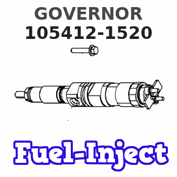
105412-1520
1054121520
MITSUBISHI
3126148500
3126148500
Rating:
Scheme ###:
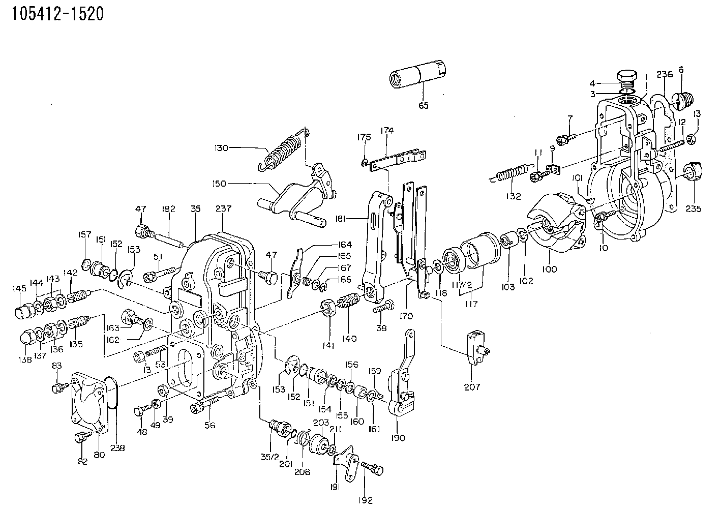
| 1. | [1] | 154000-6400 | GOVERNOR HOUSING |
| 3. | [1] | 029632-5070 | O-RING |
| 4. | [1] | 154007-2900 | CAPSULE |
| 6. | [1] | 154007-0200 | ADAPTOR |
| 7. | [1] | 020018-1840 | BLEEDER SCREW M8P1.25L18 |
| 9. | [1] | 154350-1800 | PLATE |
| 10. | [5] | 029010-6810 | BLEEDER SCREW |
| 11. | [1] | 020106-1640 | BLEEDER SCREW M6P1.0L14 |
| 12. | [1] | 154010-2900 | BLEEDER SCREW |
| 13. | [2] | 154011-0100 | HEXAGON NUT |
| 13. | [2] | 154011-0100 | HEXAGON NUT |
| 35. | [1] | 154500-3120 | GOVERNOR COVER |
| 35/2. | [1] | 154321-0400 | BUSHING |
| 38. | [1] | 154031-0100 | FLAT-HEAD SCREW |
| 39. | [1] | 013020-6020 | UNION NUT M6P1H5 |
| 47. | [2] | 154036-0300 | CAPSULE |
| 47. | [2] | 154036-0300 | CAPSULE |
| 48. | [1] | 154037-0700 | BLEEDER SCREW |
| 49. | [1] | 154038-0200 | HEXAGON NUT |
| 51. | [2] | 020106-5040 | BLEEDER SCREW |
| 53. | [1] | 154010-3100 | BLEEDER SCREW |
| 56. | [4] | 020106-3840 | BLEEDER SCREW |
| 65. | [1] | 153020-0320 | STOPPING DEVICE |
| 80. | [1] | 154060-3800 | COVER |
| 82. | [2] | 029020-6210 | BLEEDER SCREW |
| 83. | [2] | 020006-1640 | BLEEDER SCREW M6P1L16 4T |
| 100. | [1] | 154101-0520 | FLYWEIGHT ASSEMBLY |
| 101. | [1] | 025803-1610 | WOODRUFF KEY |
| 102. | [1] | 029321-2020 | LOCKING WASHER |
| 103. | [1] | 029231-2030 | UNION NUT |
| 117. | [1] | 154123-0120 | SLIDING PIECE |
| 118/1. | [0] | 029311-0010 | SHIM D14&10.1T0.2 |
| 118/1. | [0] | 029311-0180 | SHIM D14&10.1T0.3 |
| 118/1. | [0] | 029311-0190 | SHIM D14&10.1T0.40 |
| 118/1. | [0] | 029311-0210 | SHIM D14&10.1T1 |
| 118/1. | [0] | 139410-0000 | SHIM D14.0&10.1T0.5 |
| 118/1. | [0] | 139410-0100 | SHIM D14.0&10.1T1.5 |
| 118/1. | [0] | 139410-3000 | SHIM D14&10.1T2.0 |
| 118/1. | [0] | 139410-3100 | SHIM D14&10.1T3.0 |
| 118/1. | [0] | 139410-3200 | SHIM D14&10.1T4.0 |
| 130. | [1] | 154150-0100 | GOVERNOR SPRING |
| 132. | [1] | 154154-0701 | COILED SPRING |
| 135. | [1] | 154158-0920 | HEADLESS SCREW |
| 136. | [1] | 154011-1700 | UNION NUT |
| 137. | [2] | 026512-1540 | GASKET D15.4&12.2T1.50 |
| 138. | [1] | 154159-0100 | CAP NUT |
| 140. | [1] | 154175-3820 | HEADLESS SCREW |
| 141. | [1] | 029201-6010 | UNION NUT |
| 142. | [1] | 154242-0420 | HEADLESS SCREW |
| 143. | [1] | 029201-6150 | UNION NUT |
| 144. | [2] | 026516-2040 | GASKET D19.9&16.2T1 |
| 145. | [1] | 154159-1100 | CAP NUT |
| 150. | [1] | 154200-6920 | SWIVELLING LEVER |
| 151. | [1] | 154204-4300 | BUSHING |
| 151. | [1] | 154204-4300 | BUSHING |
| 152. | [2] | 029631-8020 | O-RING |
| 152. | [2] | 029631-8020 | O-RING |
| 153. | [2] | 016010-1640 | LOCKING WASHER |
| 153. | [2] | 016010-1640 | LOCKING WASHER |
| 154. | [1] | 139611-0000 | PACKING RING |
| 155. | [1] | 139411-0000 | SHIM |
| 156. | [0] | 029311-1070 | SHIM D16&11T0.5 |
| 157. | [1] | 154204-4400 | BUSHING |
| 159. | [1] | 025803-1310 | WOODRUFF KEY |
| 160. | [1] | 154206-2800 | BUSHING |
| 161. | [0] | 154206-0200 | PLAIN WASHER D19.5&11.2T1.0 |
| 162. | [1] | 029331-0240 | GASKET |
| 163. | [1] | 154401-2700 | BLEEDER SCREW |
| 164. | [1] | 154243-0220 | CONTROL LEVER |
| 165. | [1] | 154327-1900 | COILED SPRING |
| 166. | [1] | 016010-0710 | LOCKING WASHER |
| 167. | [1] | 029310-8020 | PLAIN WASHER D15&8.4T0.3 |
| 170. | [1] | 154217-4820 | FORK LEVER |
| 174. | [1] | 154230-3920 | STRAP |
| 175. | [1] | 016010-0540 | LOCKING WASHER |
| 181. | [1] | 154236-3220 | TENSIONING LEVER |
| 182. | [1] | 154237-0100 | BEARING PIN |
| 190. | [1] | 154303-9920 | CONTROL LEVER |
| 191. | [1] | 154308-4020 | CONTROL LEVER |
| 192. | [1] | 020006-3240 | BLEEDER SCREW |
| 201. | [1] | 029631-0030 | O-RING &9.8W2.3 |
| 203. | [1] | 154322-0100 | CAP |
| 207. | [1] | 154326-9020 | LEVER GROUP |
| 208. | [1] | 154327-7300 | COILED SPRING |
| 211/1. | [0] | 029311-0520 | SHIM D20.8&10.3T0.2 |
| 211/1. | [0] | 029311-0530 | SHIM D20.8&10.3T0.25 |
| 211/1. | [0] | 029311-0540 | SHIM D20.8&10.3T0.3 |
| 211/1. | [0] | 029311-0550 | SHIM D20.8&10.3T0.35 |
| 211/1. | [0] | 029311-0560 | SHIM D20.8&10.3T0.4 |
| 211/1. | [0] | 029311-0570 | SHIM D20.8&10.3T0.5 |
| 236. | [1] | 154390-0000 | GASKET |
| 237. | [1] | 154390-0300 | GASKET |
| 238. | [1] | 029635-5010 | O-RING |
Include in #1:
101891-6560
as GOVERNOR
Cross reference number
Zexel num
Bosch num
Firm num
Name
105412-1520
3126148500 MITSUBISHI
GOVERNOR
K 14JB MECHANICAL GOVERNOR GOV RSV GOV
K 14JB MECHANICAL GOVERNOR GOV RSV GOV
Information:
ROCKER ARM SHAFT ASSEMBLY
1. Fuel return line (one each head). 2. Bolts and locks (four each head).4. Remove rocker arm shaft assembly (3). Remove push rods (4).
REMOVING ROCKER ARM SHAFT ASSEMBLY
3. Rocker arm shaft assembly (one each head). 4. Push rods (eight each head).Install Rocker Arm Shaft Assemblies
1. Lubricate the cam followers, push rods, and rocker arm shaft assembly with clean engine oil (SAE 30).2. Install push rods. Position the rocker arm shaft assembly on the cylinder head.3. Install the rocker arm shaft assembly retaining bolts and locks. Tighten bolts to 18 5 lb. ft. (2.5 0.7 mkg) and bend the locks.4. Install the fuel return line.5. Adjust the intake valve clearance to .015 in. (0.38 mm) and the exhaust valve clearance to .025 in. (0.64 mm).6. Install valve cover. Install valve cover retaining bolts and tighten bolts to 120 24 lb. in. (138 28 cm.kg).Disassemble Rocker Arm Shaft Assembly
1. Remove retaining bolts and locks from each end of rocker arm shaft assembly and disassemble the rocker arm shaft assembly.
ROCKER ARM SHAFT ASSEMBLY DISASSEMBLED
1. Rocker arm shaft. 2. Rivet. 3. Washers (eight). 4. Rocker arms (two per cylinder). 5. Adjusting screw. 6. Bracket. 7. Oil supply hole.Assemble Rocker Arm Shaft Assembly
1. The oil holes in shaft (1), arms (4) and bracket (6) must be clean and free of dirt or foreign material.2. Install adjusting screws (5) into rocker arms (4) so they extend .44 in. (11.2 mm) below arm. This will avoid forcing valves into piston crowns when rocker arm assembly is installed on cylinder head.
ROCKER ARM SHAFT ASSEMBLY
1. Rocker arm shaft. 2. Rivet. 3. Washers (eight). 4. Rocker arms (two per cylinder). 5. Adjusting screw. 6. Bracket. 7. Oil supply hole.3. Install arms (4) on shaft with washers (3) positioned as shown.4. Position shaft (1) and arms (4) into bracket (6) so screws (5) are on the same side of bracket (6) as oil supply hole (7). Rivet (2) must be on top when shaft (1) is positioned into bracket (6). Later rocker arm shaft assemblies have machined flats (8). The machined flats must be on top when shaft (1) is positioned into bracket (6).
LATER ROCKER ARM SHAFT ASSEMBLY
1. Rocker arm shaft. 6. Bracket. 8. Machined flats (four per shaft).