Information governor
BOSCH
F 019 Z4E 538
f019z4e538
ZEXEL
105411-2590
1054112590
ISUZU
1157301170
1157301170

Rating:
Scheme ###:
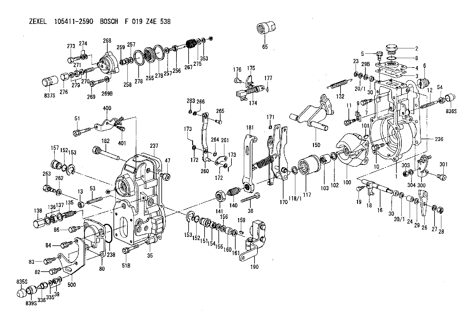
| 1. | [1] | 154004-7920 | GOVERNOR HOUSING |
| 2. | [1] | 154007-2900 | CAPSULE |
| 3. | [1] | 154390-2000 | GASKET |
| 4. | [1] | 154064-4500 | COVER |
| 5. | [4] | 020006-1640 | BLEEDER SCREW M6P1L16 4T |
| 6. | [1] | 154007-0200 | ADAPTOR |
| 7. | [1] | 020018-1840 | BLEEDER SCREW M8P1.25L18 |
| 8. | [1] | 029632-5070 | O-RING |
| 9. | [1] | 154350-1800 | PLATE |
| 10. | [5] | 029010-6810 | BLEEDER SCREW |
| 11. | [1] | 020106-1640 | BLEEDER SCREW M6P1.0L14 |
| 12. | [1] | 154013-4000 | FLAT-HEAD SCREW |
| 13. | [1] | 154011-0100 | HEXAGON NUT |
| 16. | [1] | 155004-5600 | LEVER SHAFT |
| 18. | [1] | 155003-2520 | CONTROL LEVER |
| 19. | [1] | 155006-0700 | BLEEDER SCREW |
| 20/1. | [0] | 139408-1000 | SHIM D16&8T0.5 |
| 20/1. | [0] | 139408-1300 | SHIM D16&8T0.2 |
| 20/1. | [0] | 139408-1300 | SHIM D16&8T0.2 |
| 23. | [1] | 159238-4200 | LOCKING WASHER |
| 24. | [1] | 154206-2000 | BUSHING |
| 26. | [1] | 154383-4320 | CONTROL LEVER |
| 27. | [1] | 014110-8440 | LOCKING WASHER |
| 28. | [1] | 013020-8040 | UNION NUT M8P1.25H7 |
| 29. | [2] | 154375-8900 | PLAIN WASHER |
| 29B. | [0] | 139408-1400 | SHIM |
| 29C. | [0] | 139408-1500 | SHIM |
| 30. | [2] | 139608-0000 | PACKING RING |
| 30. | [2] | 139608-0000 | PACKING RING |
| 35. | [1] | 154022-8620 | GOVERNOR COVER |
| 38. | [1] | 154031-4800 | FLAT-HEAD SCREW |
| 39. | [1] | 139208-0400 | UNION NUT |
| 47. | [1] | 154036-1200 | CAPSULE |
| 51. | [1] | 139006-7100 | BLEEDER SCREW |
| 51B. | [5] | 020106-5040 | BLEEDER SCREW |
| 53. | [1] | 154010-0100 | FLAT-HEAD SCREW |
| 54. | [1] | 154011-4900 | UNION NUT |
| 65. | [1] | 154050-6120 | STOPPING DEVICE |
| 80. | [1] | 154063-7300 | COVER |
| 82. | [1] | 020006-2040 | BLEEDER SCREW M6P1L20 4T |
| 83. | [1] | 020006-2040 | BLEEDER SCREW M6P1L20 4T |
| 84. | [1] | 029020-6260 | BLEEDER SCREW |
| 86. | [1] | 020006-1640 | BLEEDER SCREW M6P1L16 4T |
| 100. | [1] | 154101-0020 | FLYWEIGHT ASSEMBLY |
| 101. | [1] | 025803-1610 | WOODRUFF KEY |
| 102. | [1] | 029321-2020 | LOCKING WASHER |
| 103. | [1] | 029231-2030 | UNION NUT |
| 117. | [1] | 154123-2320 | SLIDING PIECE |
| 118/1. | [0] | 029311-0010 | SHIM D14&10.1T0.2 |
| 118/1. | [0] | 029311-0180 | SHIM D14&10.1T0.3 |
| 118/1. | [0] | 029311-0190 | SHIM D14&10.1T0.40 |
| 118/1. | [0] | 029311-0210 | SHIM D14&10.1T1 |
| 118/1. | [0] | 139410-0000 | SHIM D14.0&10.1T0.5 |
| 118/1. | [0] | 139410-0100 | SHIM D14.0&10.1T1.5 |
| 118/1. | [0] | 139410-3000 | SHIM D14&10.1T2.0 |
| 118/1. | [0] | 139410-3100 | SHIM D14&10.1T3.0 |
| 118/1. | [0] | 139410-3200 | SHIM D14&10.1T4.0 |
| 132. | [1] | 154154-0701 | COILED SPRING |
| 135. | [1] | 154158-1320 | HEADLESS SCREW |
| 136. | [1] | 029201-2290 | UNION NUT |
| 137. | [2] | 026512-1540 | GASKET D15.4&12.2T1.50 |
| 138. | [1] | 154159-1200 | CAP NUT |
| 140. | [1] | 154185-2120 | HEADLESS SCREW |
| 141. | [1] | 029201-6010 | UNION NUT |
| 150. | [1] | 154200-7220 | SWIVELLING LEVER |
| 151. | [1] | 154204-4300 | BUSHING |
| 152. | [2] | 139718-0600 | O-RING |
| 152. | [2] | 139718-0600 | O-RING |
| 153. | [2] | 016010-1640 | LOCKING WASHER |
| 153. | [2] | 016010-1640 | LOCKING WASHER |
| 154. | [1] | 139611-0400 | PACKING RING |
| 155. | [1] | 139411-0000 | SHIM |
| 156. | [0] | 029311-1070 | SHIM D16&11T0.5 |
| 157. | [1] | 154204-4400 | BUSHING |
| 159. | [1] | 025803-1310 | WOODRUFF KEY |
| 160. | [1] | 154206-2800 | BUSHING |
| 161. | [0] | 154206-0200 | PLAIN WASHER D19.5&11.2T1.0 |
| 170. | [1] | 154217-0520 | FORK LEVER |
| 171. | [1] | 016010-0540 | LOCKING WASHER |
| 172. | [3] | 029310-5170 | SHIM D8&5.3T0.5 |
| 172. | [3] | 029310-5170 | SHIM D8&5.3T0.5 |
| 173. | [2] | 025520-1210 | SPLIT PIN |
| 173. | [2] | 025520-1210 | SPLIT PIN |
| 174. | [1] | 154235-4820 | STRAP |
| 175. | [1] | 154232-3000 | CONNECTOR |
| 176. | [1] | 154222-5800 | BEARING PIN |
| 177. | [1] | 155402-3800 | SAFETY PIN |
| 181. | [1] | 154239-1720 | TENSIONING LEVER |
| 182. | [1] | 154237-1100 | BEARING PIN |
| 190. | [1] | 154342-3720 | CONTROL LEVER |
| 236. | [1] | 154390-1300 | GASKET |
| 237. | [1] | 154390-0300 | GASKET |
| 238. | [1] | 029635-2020 | O-RING |
| 255. | [1] | 154400-7420 | DIAPHRAGM |
| 256. | [1] | 154400-4800 | STOP PIN |
| 257. | [2] | 029330-8050 | GASKET |
| 257. | [2] | 029330-8050 | GASKET |
| 258. | [1] | 139308-0700 | LOCKING WASHER |
| 259. | [1] | 013030-6040 | UNION NUT M6P1H3.6 |
| 260. | [1] | 154401-3720 | CONTROL LEVER |
| 261. | [1] | 154401-1120 | STRAP |
| 262. | [1] | 026510-1440 | GASKET D13.9&10.2T1 |
| 263. | [1] | 154401-2100 | BLEEDER SCREW |
| 264. | [1] | 016010-0540 | LOCKING WASHER |
| 265. | [1] | 154222-6200 | BEARING PIN |
| 266. | [1] | 029300-4010 | PLAIN WASHER |
| 267. | [1] | 154403-6700 | COILED SPRING |
| 268. | [1] | 154404-5600 | COVER |
| 269. | [3] | 154062-2900 | BLEEDER SCREW |
| 269B. | [3] | 014110-6440 | LOCKING WASHER |
| 270. | [1] | 154034-1900 | FLAT-HEAD SCREW |
| 271. | [1] | 013030-6040 | UNION NUT M6P1H3.6 |
| 273. | [1] | 029731-0180 | EYE BOLT |
| 274. | [2] | 026510-1340 | GASKET D13.4&10.2T1 |
| 275. | [0] | 029312-0180 | SHIM D25.5&20T0.5 |
| 275B. | [0] | 029312-0210 | SHIM D25.5&20T0.2 |
| 276. | [1] | 154035-1600 | CAP NUT |
| 278. | [2] | 154413-2600 | GASKET |
| 278. | [2] | 154413-2600 | GASKET |
| 279. | [2] | 026506-1040 | GASKET D9.9&6.2T1 |
| 283. | [1] | 016010-0440 | LOCKING WASHER |
| 300. | [1] | 154358-9420 | BRACKET |
| 301. | [1] | 020118-1640 | BLEEDER SCREW |
| 303. | [1] | 154011-1100 | UNION NUT |
| 304. | [1] | 029300-8320 | SHIM |
| 335. | [2] | 026508-1140 | GASKET D11.4&8.2T1 |
| 336. | [1] | 154035-2900 | CAP NUT |
| 353. | [2] | 029310-9080 | SHIM D16&9T1.7 |
| 400. | [1] | 154376-6820 | BRACKET |
| 401. | [1] | 020006-1240 | BLEEDER SCREW M6P1L12 4T |
| 500. | [1] | 154358-7200 | BRACKET |
| 835S. | [1] | 154062-4020 | CAP |
| 836S. | [1] | 154062-3520 | CAP |
| 837S. | [1] | 154062-2720 | CAP |
| 839S. | [1] | 154062-3900 | ADAPTOR |
Include in #1:
101605-0250
as GOVERNOR
Cross reference number
Zexel num
Bosch num
Firm num
Name
105411-2590
1157301170 ISUZU
GOVERNOR
K 14JB MECHANICAL GOVERNOR GOV RSV GOV
K 14JB MECHANICAL GOVERNOR GOV RSV GOV
Information:
1. Remove all of bolts (1) and bolts (2) and (3).2. Use two 3/8"-16 NC forcing screws and remove stator (4) from the flywheel housing. 3. If necessary remove the lip type seal from stator (4) with a hammer and punch. 4. Remove the six O-ring seals (6) from the flywheel housing.5. Remove rotor (5) from the crankshaft. 6. Remove the seal ring from carrier (8).7. If necessary remove carrier (8) and sleeve (7) from rotor (5). The carrier and sleeve will have damage after removal. Use new parts for replacement.Install BrakeSaver
1. If the carrier and sleeve were removed from the rotor, heat the new parts to a maximum temperature of 300° F (149° C). 2. Install carrier (2) on rotor (3).3. Put 7M7260 Liquid Gasket Material on the outside diameter (4) of rotor (3) and let it dry. Install sleeve (1) on rotor (3) as shown. 4. Install seal ring (5) in the carrier. 5. Install two 3/4"-16 NF guide bolts (6) a minimum of 5 in. long in the crankshaft.6. Make sure the O-ring seal is on rear face of the crankshaft seal carrier and install rotor (3) on the guide bolts with the marked bolt hole of the rotor in alignment with the marked hole of the crankshaft. 7. Use tool (A) and a press to install the seal in stator (7) as shown. 8. Install O-ring seal in position on stator (7). Install O-ring seals (8) in the flywheel housing.9. Put stator (7) in position on the flywheel housing. 10. Put 9S3263 Thread Lock on the threads of the bolts that hold the stator and install them. Tighten all of bolts (9) evenly to a torque of 40 5 lb. ft. (55 7 N m). Tighten bolts (10) and (11) to a torque of 90 10 lb. ft. (120 14 N m).end by: a) install flywheel
1. If the carrier and sleeve were removed from the rotor, heat the new parts to a maximum temperature of 300° F (149° C). 2. Install carrier (2) on rotor (3).3. Put 7M7260 Liquid Gasket Material on the outside diameter (4) of rotor (3) and let it dry. Install sleeve (1) on rotor (3) as shown. 4. Install seal ring (5) in the carrier. 5. Install two 3/4"-16 NF guide bolts (6) a minimum of 5 in. long in the crankshaft.6. Make sure the O-ring seal is on rear face of the crankshaft seal carrier and install rotor (3) on the guide bolts with the marked bolt hole of the rotor in alignment with the marked hole of the crankshaft. 7. Use tool (A) and a press to install the seal in stator (7) as shown. 8. Install O-ring seal in position on stator (7). Install O-ring seals (8) in the flywheel housing.9. Put stator (7) in position on the flywheel housing. 10. Put 9S3263 Thread Lock on the threads of the bolts that hold the stator and install them. Tighten all of bolts (9) evenly to a torque of 40 5 lb. ft. (55 7 N m). Tighten bolts (10) and (11) to a torque of 90 10 lb. ft. (120 14 N m).end by: a) install flywheel