Information governor
BOSCH
F 019 Z2E 683
f019z2e683
ZEXEL
105411-2381
1054112381
ISUZU
8973086860
8973086860
Rating:
Scheme ###:
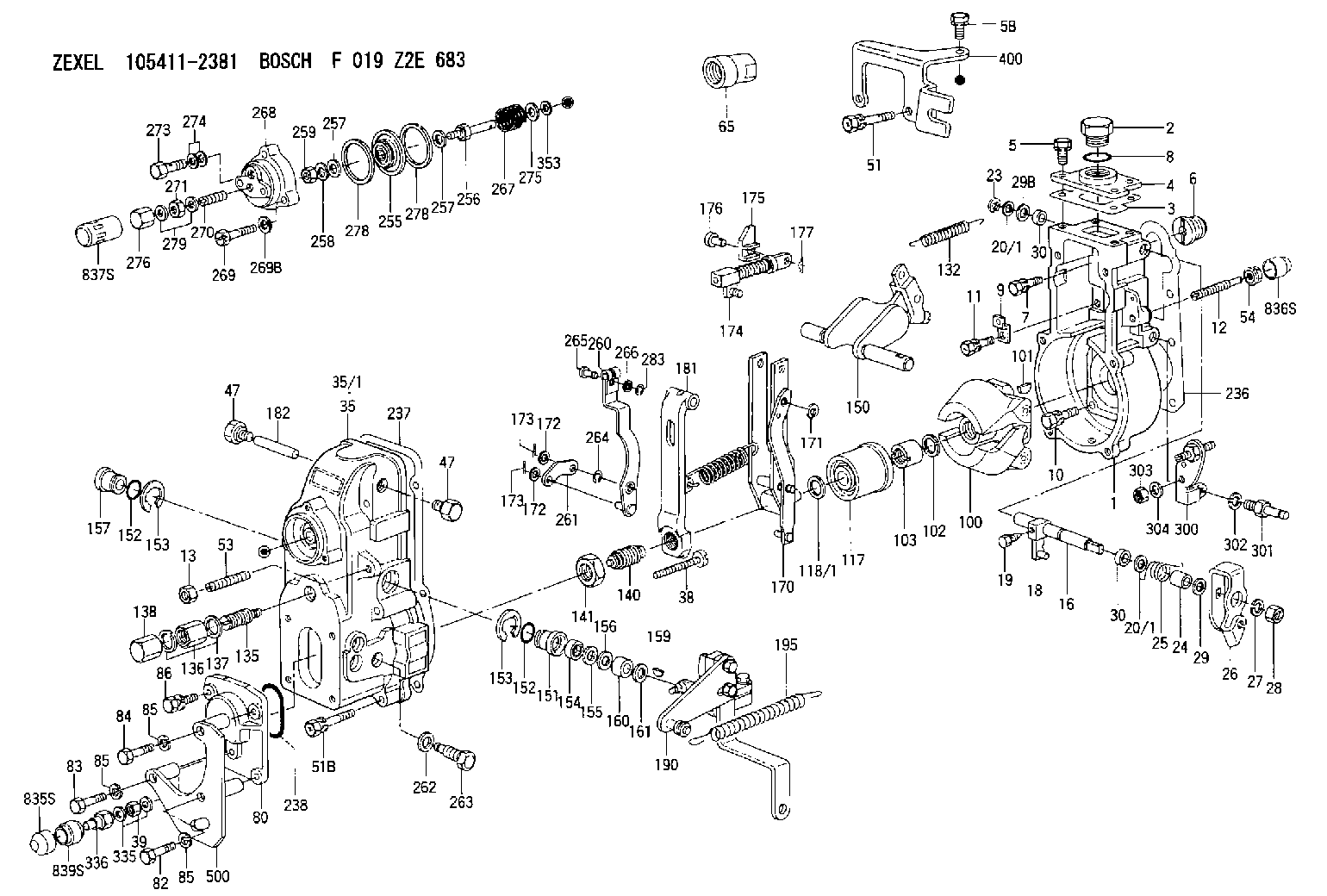
| 1. | [1] | 154004-7920 | GOVERNOR HOUSING |
| 2. | [1] | 154007-2900 | CAPSULE |
| 3. | [1] | 154390-2000 | GASKET |
| 4. | [1] | 154064-4500 | COVER |
| 5. | [3] | 020006-1640 | BLEEDER SCREW M6P1L16 4T |
| 5B. | [1] | 020006-2040 | BLEEDER SCREW M6P1L20 4T |
| 6. | [1] | 154007-0200 | ADAPTOR |
| 7. | [1] | 020018-1840 | BLEEDER SCREW M8P1.25L18 |
| 8. | [1] | 029632-5070 | O-RING |
| 9. | [1] | 154350-1800 | PLATE |
| 10. | [5] | 029010-6810 | BLEEDER SCREW |
| 11. | [1] | 020106-1640 | BLEEDER SCREW M6P1.0L14 |
| 12. | [1] | 154013-4000 | FLAT-HEAD SCREW |
| 13. | [1] | 154011-0100 | HEXAGON NUT |
| 16. | [1] | 155004-5600 | LEVER SHAFT |
| 18. | [1] | 155003-2520 | CONTROL LEVER |
| 19. | [1] | 155006-0700 | BLEEDER SCREW |
| 20/1. | [0] | 139408-1000 | SHIM D16&8T0.5 |
| 20/1. | [0] | 139408-1300 | SHIM D16&8T0.2 |
| 20/1. | [0] | 139408-1300 | SHIM D16&8T0.2 |
| 23. | [1] | 159238-4200 | LOCKING WASHER |
| 24. | [1] | 154206-2000 | BUSHING |
| 25. | [1] | 154327-4200 | COILED SPRING |
| 26. | [1] | 154382-5400 | CONTROL LEVER |
| 27. | [1] | 014110-8440 | LOCKING WASHER |
| 28. | [1] | 013020-8040 | UNION NUT M8P1.25H7 |
| 29. | [2] | 154375-8900 | PLAIN WASHER |
| 29B. | [0] | 139408-1400 | SHIM |
| 29C. | [0] | 139408-1500 | SHIM |
| 30. | [2] | 139608-0000 | PACKING RING |
| 30. | [2] | 139608-0000 | PACKING RING |
| 35. | [1] | 154022-8920 | GOVERNOR COVER |
| 35/1. | [1] | 154022-8900 | GOVERNOR COVER |
| 38. | [1] | 154031-1300 | FLAT-HEAD SCREW |
| 39. | [1] | 139206-0600 | UNION NUT |
| 47. | [2] | 154036-0300 | CAPSULE |
| 47. | [2] | 154036-0300 | CAPSULE |
| 51. | [2] | 020106-5040 | BLEEDER SCREW |
| 51B. | [4] | 020106-5040 | BLEEDER SCREW |
| 53. | [1] | 154010-0100 | FLAT-HEAD SCREW |
| 54. | [1] | 154011-4900 | UNION NUT |
| 65. | [1] | 154050-6120 | STOPPING DEVICE |
| 80. | [1] | 154064-4300 | COVER |
| 82. | [1] | 029000-6870 | BLEEDER SCREW |
| 83. | [1] | 029000-6870 | BLEEDER SCREW |
| 84. | [1] | 020506-3840 | BLEEDER SCREW |
| 85. | [3] | 014110-6440 | LOCKING WASHER |
| 85. | [3] | 014110-6440 | LOCKING WASHER |
| 85. | [3] | 014110-6440 | LOCKING WASHER |
| 86. | [1] | 020006-1640 | BLEEDER SCREW M6P1L16 4T |
| 100. | [1] | 154101-0020 | FLYWEIGHT ASSEMBLY |
| 101. | [1] | 025803-1610 | WOODRUFF KEY |
| 102. | [1] | 029321-2020 | LOCKING WASHER |
| 103. | [1] | 029231-2030 | UNION NUT |
| 117. | [1] | 154123-0120 | SLIDING PIECE |
| 118/1. | [0] | 029311-0010 | SHIM D14&10.1T0.2 |
| 118/1. | [0] | 029311-0180 | SHIM D14&10.1T0.3 |
| 118/1. | [0] | 029311-0190 | SHIM D14&10.1T0.40 |
| 118/1. | [0] | 029311-0210 | SHIM D14&10.1T1 |
| 118/1. | [0] | 139410-0000 | SHIM D14.0&10.1T0.5 |
| 118/1. | [0] | 139410-0100 | SHIM D14.0&10.1T1.5 |
| 118/1. | [0] | 139410-3000 | SHIM D14&10.1T2.0 |
| 118/1. | [0] | 139410-3100 | SHIM D14&10.1T3.0 |
| 118/1. | [0] | 139410-3200 | SHIM D14&10.1T4.0 |
| 132. | [1] | 154154-0701 | COILED SPRING |
| 135. | [1] | 154158-1320 | HEADLESS SCREW |
| 136. | [1] | 029201-2290 | UNION NUT |
| 137. | [2] | 026512-1540 | GASKET D15.4&12.2T1.50 |
| 138. | [1] | 154159-1200 | CAP NUT |
| 140. | [1] | 154178-9220 | HEADLESS SCREW |
| 141. | [1] | 029201-6010 | UNION NUT |
| 150. | [1] | 154200-7220 | SWIVELLING LEVER |
| 151. | [1] | 154204-4300 | BUSHING |
| 152. | [2] | 139718-0600 | O-RING |
| 152. | [2] | 139718-0600 | O-RING |
| 153. | [2] | 016010-1640 | LOCKING WASHER |
| 153. | [2] | 016010-1640 | LOCKING WASHER |
| 154. | [1] | 139611-0400 | PACKING RING |
| 155. | [1] | 139411-0000 | SHIM |
| 156. | [0] | 029311-1070 | SHIM D16&11T0.5 |
| 157. | [1] | 154204-4400 | BUSHING |
| 159. | [1] | 025803-1310 | WOODRUFF KEY |
| 160. | [1] | 154206-2800 | BUSHING |
| 161. | [0] | 154206-0200 | PLAIN WASHER D19.5&11.2T1.0 |
| 170. | [1] | 154217-0520 | FORK LEVER |
| 171. | [1] | 016010-0540 | LOCKING WASHER |
| 172. | [3] | 029310-5170 | SHIM D8&5.3T0.5 |
| 172. | [3] | 029310-5170 | SHIM D8&5.3T0.5 |
| 173. | [2] | 025520-1210 | SPLIT PIN |
| 173. | [2] | 025520-1210 | SPLIT PIN |
| 174. | [1] | 154234-4020 | STRAP |
| 175. | [1] | 154232-3000 | CONNECTOR |
| 176. | [1] | 154222-5800 | BEARING PIN |
| 177. | [1] | 155402-3800 | SAFETY PIN |
| 181. | [1] | 154239-1720 | TENSIONING LEVER |
| 182. | [1] | 154237-0100 | BEARING PIN |
| 190. | [1] | 154396-6920 | CONTROL LEVER |
| 195. | [1] | 154314-2600 | COILED SPRING |
| 236. | [1] | 154390-1300 | GASKET |
| 237. | [1] | 154390-0300 | GASKET |
| 238. | [1] | 029635-2020 | O-RING |
| 255. | [1] | 154400-7420 | DIAPHRAGM |
| 256. | [1] | 154400-4800 | STOP PIN |
| 257. | [2] | 029330-8050 | GASKET |
| 257. | [2] | 029330-8050 | GASKET |
| 258. | [1] | 139308-0700 | LOCKING WASHER |
| 259. | [1] | 013030-6040 | UNION NUT M6P1H3.6 |
| 260. | [1] | 154401-3720 | CONTROL LEVER |
| 261. | [1] | 154401-1120 | STRAP |
| 262. | [1] | 026510-1440 | GASKET D13.9&10.2T1 |
| 263. | [1] | 154401-2100 | BLEEDER SCREW |
| 264. | [1] | 016010-0540 | LOCKING WASHER |
| 265. | [1] | 154222-6200 | BEARING PIN |
| 266. | [1] | 029300-4010 | PLAIN WASHER |
| 267. | [1] | 154403-6700 | COILED SPRING |
| 268. | [1] | 154404-5600 | COVER |
| 269. | [3] | 154062-2900 | BLEEDER SCREW |
| 269B. | [3] | 014110-6440 | LOCKING WASHER |
| 270. | [1] | 154034-1900 | FLAT-HEAD SCREW |
| 271. | [1] | 013030-6040 | UNION NUT M6P1H3.6 |
| 273. | [1] | 029731-0180 | EYE BOLT |
| 274. | [2] | 026510-1340 | GASKET D13.4&10.2T1 |
| 275. | [0] | 029312-0180 | SHIM D25.5&20T0.5 |
| 275B. | [0] | 029312-0210 | SHIM D25.5&20T0.2 |
| 276. | [1] | 154035-1600 | CAP NUT |
| 278. | [2] | 154413-2600 | GASKET |
| 278. | [2] | 154413-2600 | GASKET |
| 279. | [2] | 026506-1040 | GASKET D9.9&6.2T1 |
| 283. | [1] | 016010-0440 | LOCKING WASHER |
| 300. | [1] | 154358-9420 | BRACKET |
| 301. | [1] | 154013-3420 | BLEEDER SCREW |
| 302. | [1] | 014110-8440 | LOCKING WASHER |
| 303. | [1] | 154011-1100 | UNION NUT |
| 304. | [1] | 029300-8320 | SHIM |
| 335. | [2] | 026506-1040 | GASKET D9.9&6.2T1 |
| 336. | [1] | 154035-2800 | CAP NUT |
| 353. | [3] | 029310-9080 | SHIM D16&9T1.7 |
| 400. | [1] | 154375-8320 | BRACKET |
| 500. | [1] | 154376-6320 | BRACKET |
| 835S. | [1] | 154062-4020 | CAP |
| 836S. | [1] | 154062-3520 | CAP |
| 837S. | [1] | 154062-2720 | CAP |
| 839S. | [1] | 154062-3800 | ADAPTOR |
Include in #1:
101402-7921
as GOVERNOR
Cross reference number
Zexel num
Bosch num
Firm num
Name
Information:
start by: a) remove fuel injection pump housing and governor1. Put the fuel injection pump housing on tool (A). 2. Remove bolts (1). 3. Remove bolt (2). Remove adapter housing (3) from the pump housing. 4. Remove bolts (4) and (5). Loosen bolt (6). 5. Remove governor housing (7) from the pump housing. 6. Remove spring (12), wave washer (11) and guide (10). Remove seat (8) and over fueling spring (9). 7. Pull shaft (13) up and remove it. Remove lever (14) from the housing. 8. Remove riser (follower) (17) from the shaft. Remove ring (15) and lever (16). 9. Remove cover (18) with tool (B). Tool (B) can cause damage to the cover. Always inspect the cover and install a new cover if needed.10. Install the timing pin to prevent the camshaft from turning. 11. Remove three bolts (19) that hold the flyweight assembly to the camshaft. Remove the flyweight assembly from the pump housing.12. Remove the timing pin.Connection Of Governor To Fuel Injection Pump Housing
1. Put the fuel injection pump housing on tool (A).2. Install the timing pin to prevent the camshaft from turning. 3. Put flyweight assembly (1) in position on the camshaft.
Be sure pin (2) that holds the shaft is in the correct position on back of the flyweight assembly.
4. Install new bolts for the flyweight assembly. The bolts for the flyweight assembly have a locking material on the threads and must not be used more than one time. 5. Install the cover over the flyweight assembly with tool (B). 6. Grind a taper on the bottom edge of a 1/8" screwdriver (3). Install the screwdriver through the bolt hole in the governor housing. The screwdriver must fit evenly against the flyweight assembly cover. Make a mark (stake) in four places around the cover in line with the groove in the camshaft.
Never install a used flyweight cover that is bent.
7. Install lever (4) on the dowel. Install ring (5). 8. Put riser (follower) (6) in position between the flyweights. Lift the flyweight up with a piece of wire and push the riser (follower) forward. 9. Put lever (10) in position. Lever (10) will be in the correct position when the lever end is in the groove of riser (follower) (6) and the ball end is engaged in sleeve shaft lever (9).
If lever (10) is not installed correctly, the governor can not operate and can cause the engine to over speed.
10. Install O-ring (7). Install shaft (8) to hold lever (10) in place. 11. Install over fueling spring (12) and seat (11) on the shaft. 12. Install guide (13), (wave) washer (14) and spring (15) in the governor housing.13. Put the governor housing on the fuel injection pump housing and install the bolts.end by: a) install adapter housing and leversb) install fuel injection pump housing and governorc) make adjustment of fuel system setting (See Fuel System Setting in Testing and Adjusting)