Information governor
BOSCH
F 019 Z2E 574
f019z2e574
ZEXEL
105411-2380
1054112380
ISUZU
8973012100
8973012100
Rating:
Scheme ###:
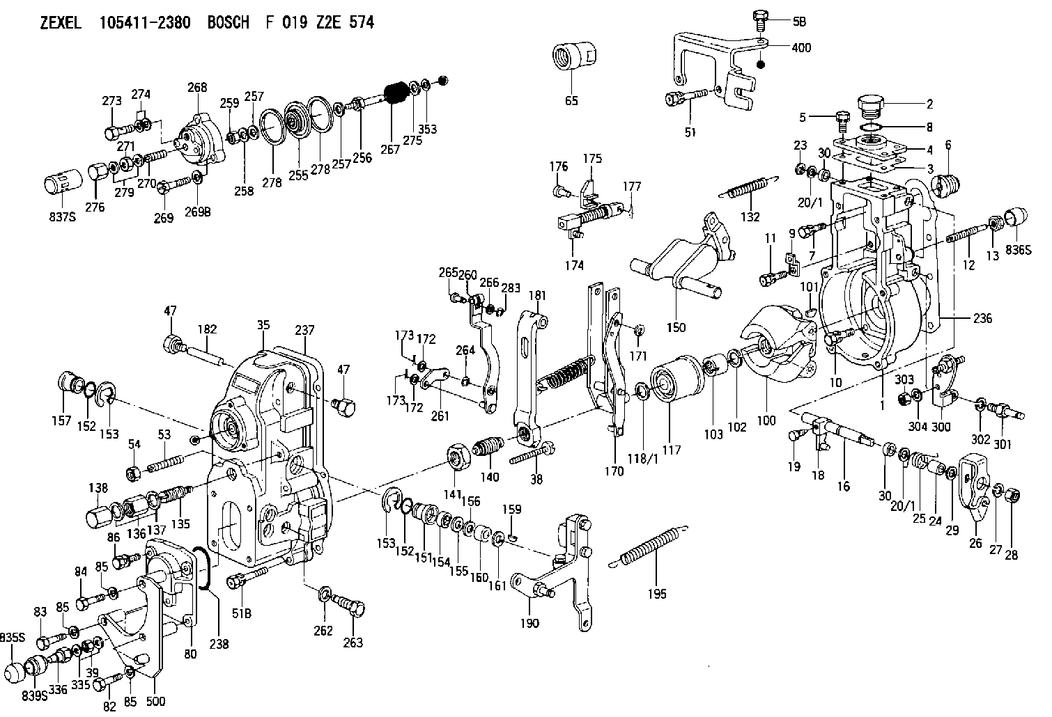
| 1. | [1] | 154004-7920 | GOVERNOR HOUSING |
| 2. | [1] | 154007-2900 | CAPSULE |
| 3. | [1] | 154390-2000 | GASKET |
| 4. | [1] | 154064-4500 | COVER |
| 5. | [3] | 020006-1640 | BLEEDER SCREW M6P1L16 4T |
| 5B. | [1] | 020006-2040 | BLEEDER SCREW M6P1L20 4T |
| 6. | [1] | 154007-0200 | ADAPTOR |
| 7. | [1] | 020018-1840 | BLEEDER SCREW M8P1.25L18 |
| 8. | [1] | 029632-5070 | O-RING |
| 9. | [1] | 154350-1800 | PLATE |
| 10. | [5] | 029010-6810 | BLEEDER SCREW |
| 11. | [1] | 020106-1640 | BLEEDER SCREW M6P1.0L14 |
| 12. | [1] | 154013-4000 | FLAT-HEAD SCREW |
| 13. | [1] | 154011-0100 | HEXAGON NUT |
| 16. | [1] | 155004-5600 | LEVER SHAFT |
| 18. | [1] | 155003-2520 | CONTROL LEVER |
| 19. | [1] | 155006-0700 | BLEEDER SCREW |
| 20/1. | [0] | 139408-1000 | SHIM D16&8T0.5 |
| 20/1. | [0] | 139408-1300 | SHIM D16&8T0.2 |
| 20/1. | [0] | 139408-1300 | SHIM D16&8T0.2 |
| 23. | [1] | 159238-4200 | LOCKING WASHER |
| 24. | [1] | 154206-2000 | BUSHING |
| 25. | [1] | 154327-4200 | COILED SPRING |
| 26. | [1] | 154382-5400 | CONTROL LEVER |
| 27. | [1] | 014110-8440 | LOCKING WASHER |
| 28. | [1] | 013020-8040 | UNION NUT M8P1.25H7 |
| 29. | [2] | 154375-8900 | PLAIN WASHER |
| 29B. | [0] | 139408-1400 | SHIM |
| 29C. | [0] | 139408-1500 | SHIM |
| 30. | [2] | 139608-0000 | PACKING RING |
| 30. | [2] | 139608-0000 | PACKING RING |
| 35. | [1] | 154022-6620 | GOVERNOR COVER |
| 38. | [1] | 154031-1300 | FLAT-HEAD SCREW |
| 39. | [1] | 139206-0600 | UNION NUT |
| 47. | [2] | 154036-0300 | CAPSULE |
| 47. | [2] | 154036-0300 | CAPSULE |
| 51. | [2] | 020106-5040 | BLEEDER SCREW |
| 51B. | [4] | 020106-5040 | BLEEDER SCREW |
| 53. | [1] | 154010-0100 | FLAT-HEAD SCREW |
| 54. | [1] | 154011-4900 | UNION NUT |
| 65. | [1] | 154050-6120 | STOPPING DEVICE |
| 80. | [1] | 154064-4300 | COVER |
| 82. | [1] | 029000-6870 | BLEEDER SCREW |
| 83. | [1] | 029000-6870 | BLEEDER SCREW |
| 84. | [1] | 020506-3840 | BLEEDER SCREW |
| 85. | [3] | 014110-6440 | LOCKING WASHER |
| 85. | [3] | 014110-6440 | LOCKING WASHER |
| 85. | [3] | 014110-6440 | LOCKING WASHER |
| 86. | [1] | 020006-1640 | BLEEDER SCREW M6P1L16 4T |
| 100. | [1] | 154101-0020 | FLYWEIGHT ASSEMBLY |
| 101. | [1] | 025803-1610 | WOODRUFF KEY |
| 102. | [1] | 029321-2020 | LOCKING WASHER |
| 103. | [1] | 029231-2030 | UNION NUT |
| 117. | [1] | 154123-0120 | SLIDING PIECE |
| 118/1. | [0] | 029311-0010 | SHIM D14&10.1T0.2 |
| 118/1. | [0] | 029311-0180 | SHIM D14&10.1T0.3 |
| 118/1. | [0] | 029311-0190 | SHIM D14&10.1T0.40 |
| 118/1. | [0] | 029311-0210 | SHIM D14&10.1T1 |
| 118/1. | [0] | 139410-0000 | SHIM D14.0&10.1T0.5 |
| 118/1. | [0] | 139410-0100 | SHIM D14.0&10.1T1.5 |
| 118/1. | [0] | 139410-3000 | SHIM D14&10.1T2.0 |
| 118/1. | [0] | 139410-3100 | SHIM D14&10.1T3.0 |
| 118/1. | [0] | 139410-3200 | SHIM D14&10.1T4.0 |
| 132. | [1] | 154154-0701 | COILED SPRING |
| 135. | [1] | 154158-1320 | HEADLESS SCREW |
| 136. | [1] | 029201-2290 | UNION NUT |
| 137. | [2] | 026512-1540 | GASKET D15.4&12.2T1.50 |
| 138. | [1] | 154159-1200 | CAP NUT |
| 140. | [1] | 154178-9220 | HEADLESS SCREW |
| 141. | [1] | 029201-6010 | UNION NUT |
| 150. | [1] | 154200-7220 | SWIVELLING LEVER |
| 151. | [1] | 154204-4300 | BUSHING |
| 152. | [2] | 139718-0600 | O-RING |
| 152. | [2] | 139718-0600 | O-RING |
| 153. | [2] | 016010-1640 | LOCKING WASHER |
| 153. | [2] | 016010-1640 | LOCKING WASHER |
| 154. | [1] | 139611-0400 | PACKING RING |
| 155. | [1] | 139411-0000 | SHIM |
| 156. | [0] | 029311-1070 | SHIM D16&11T0.5 |
| 157. | [1] | 154204-4400 | BUSHING |
| 159. | [1] | 025803-1310 | WOODRUFF KEY |
| 160. | [1] | 154206-2800 | BUSHING |
| 161. | [0] | 154206-0200 | PLAIN WASHER D19.5&11.2T1.0 |
| 170. | [1] | 154217-0520 | FORK LEVER |
| 171. | [1] | 016010-0540 | LOCKING WASHER |
| 172. | [3] | 029310-5170 | SHIM D8&5.3T0.5 |
| 172. | [3] | 029310-5170 | SHIM D8&5.3T0.5 |
| 173. | [2] | 025520-1210 | SPLIT PIN |
| 173. | [2] | 025520-1210 | SPLIT PIN |
| 174. | [1] | 154234-4020 | STRAP |
| 175. | [1] | 154232-3000 | CONNECTOR |
| 176. | [1] | 154222-5800 | BEARING PIN |
| 177. | [1] | 155402-3800 | SAFETY PIN |
| 181. | [1] | 154239-1720 | TENSIONING LEVER |
| 182. | [1] | 154237-0100 | BEARING PIN |
| 190. | [1] | 154396-6920 | CONTROL LEVER |
| 195. | [1] | 154314-2600 | COILED SPRING |
| 236. | [1] | 154390-1300 | GASKET |
| 237. | [1] | 154390-0300 | GASKET |
| 238. | [1] | 029635-2020 | O-RING |
| 255. | [1] | 154400-7420 | DIAPHRAGM |
| 256. | [1] | 154400-4800 | STOP PIN |
| 257. | [2] | 029330-8050 | GASKET |
| 257. | [2] | 029330-8050 | GASKET |
| 258. | [1] | 139308-0700 | LOCKING WASHER |
| 259. | [1] | 013030-6040 | UNION NUT M6P1H3.6 |
| 260. | [1] | 154401-3720 | CONTROL LEVER |
| 261. | [1] | 154401-1120 | STRAP |
| 262. | [1] | 026510-1440 | GASKET D13.9&10.2T1 |
| 263. | [1] | 154401-2100 | BLEEDER SCREW |
| 264. | [1] | 016010-0540 | LOCKING WASHER |
| 265. | [1] | 154222-6200 | BEARING PIN |
| 266. | [1] | 029300-4010 | PLAIN WASHER |
| 267. | [1] | 154403-6700 | COILED SPRING |
| 268. | [1] | 154404-5600 | COVER |
| 269. | [3] | 154062-2900 | BLEEDER SCREW |
| 269B. | [3] | 014110-6440 | LOCKING WASHER |
| 270. | [1] | 154034-1900 | FLAT-HEAD SCREW |
| 271. | [1] | 013030-6040 | UNION NUT M6P1H3.6 |
| 273. | [1] | 029731-0180 | EYE BOLT |
| 274. | [2] | 026510-1340 | GASKET D13.4&10.2T1 |
| 275. | [0] | 029312-0180 | SHIM D25.5&20T0.5 |
| 275B. | [0] | 029312-0210 | SHIM D25.5&20T0.2 |
| 276. | [1] | 154035-1600 | CAP NUT |
| 278. | [2] | 154413-2600 | GASKET |
| 278. | [2] | 154413-2600 | GASKET |
| 279. | [2] | 026506-1040 | GASKET D9.9&6.2T1 |
| 283. | [1] | 016010-0440 | LOCKING WASHER |
| 300. | [1] | 154358-9420 | BRACKET |
| 301. | [1] | 154013-3420 | BLEEDER SCREW |
| 302. | [1] | 014110-8440 | LOCKING WASHER |
| 303. | [1] | 154011-1100 | UNION NUT |
| 304. | [1] | 029300-8320 | SHIM |
| 335. | [2] | 026506-1040 | GASKET D9.9&6.2T1 |
| 336. | [1] | 154035-2800 | CAP NUT |
| 353. | [3] | 029310-9080 | SHIM D16&9T1.7 |
| 400. | [1] | 154375-8320 | BRACKET |
| 500. | [1] | 154376-6320 | BRACKET |
| 835S. | [1] | 154062-4020 | CAP |
| 836S. | [1] | 154062-3520 | CAP |
| 837S. | [1] | 154062-2720 | CAP |
| 839S. | [1] | 154062-3800 | ADAPTOR |
Include in #1:
101402-7920
as GOVERNOR
Cross reference number
Zexel num
Bosch num
Firm num
Name
Information:
start by: a) remove fuel injection pump housing and governor 1. Remove the fuel from the pump housing. Install the pump housing on tool (A).2. Remove priming pump (1). Remove the fuel filter.3. Remove fuel filter base assembly (2) from the top cover. 4. Remove elbow (3) and disc (4) from the fuel base assembly. The function of disc (4) is to keep the fuel in the pump housing from returning to the tank when the engine is not in operation. If the fuel tank is higher than the fuel pump housing, the disc is not needed. 5. Remove cover (5) and the fuel channel from the pump housing.6. Remove spring and bypass valve (6) from the housing.7. Remove check valve (7).8. Remove the fuel channel from cover (5). 9. Remove check valve (9) and spring from fuel channel (8) if so equipped. Earlier fuel systems have two check valves (7) and (9). Check valve (9) is not needed. Remove check valve (9) and the spring. Fill the hole in the fuel channel with weld, a rivet or a sheet metal drive screw that has sealant on it.Install Fuel Check Valve And Bypass Valve
1. Install fuel channel (1) on cover (2).2. Install spring and bypass valve (3) in the housing with the rounded end up. 3. Install check valve (4) evenly in the pump housing. Do not install a check valve that is bent.4. Install the cover on the pump housing. Be sure the bypass valve spring is in the cover groove. 5. Install disc (5). Install the elbow on the fuel base filter assembly. 6. Install fuel filter base assembly (6) on cover (2).7. Install priming pump (7). Install the fuel filter.8. Remove the fuel injection pump housing and governor from tool (A).end by: a) install fuel injection pump housing and governor
1. Install fuel channel (1) on cover (2).2. Install spring and bypass valve (3) in the housing with the rounded end up. 3. Install check valve (4) evenly in the pump housing. Do not install a check valve that is bent.4. Install the cover on the pump housing. Be sure the bypass valve spring is in the cover groove. 5. Install disc (5). Install the elbow on the fuel base filter assembly. 6. Install fuel filter base assembly (6) on cover (2).7. Install priming pump (7). Install the fuel filter.8. Remove the fuel injection pump housing and governor from tool (A).end by: a) install fuel injection pump housing and governor