Information governor
BOSCH
9 420 611 121
9420611121
ZEXEL
105411-1580
1054111580
ISUZU
1157705720
1157705720
Rating:
Scheme ###:
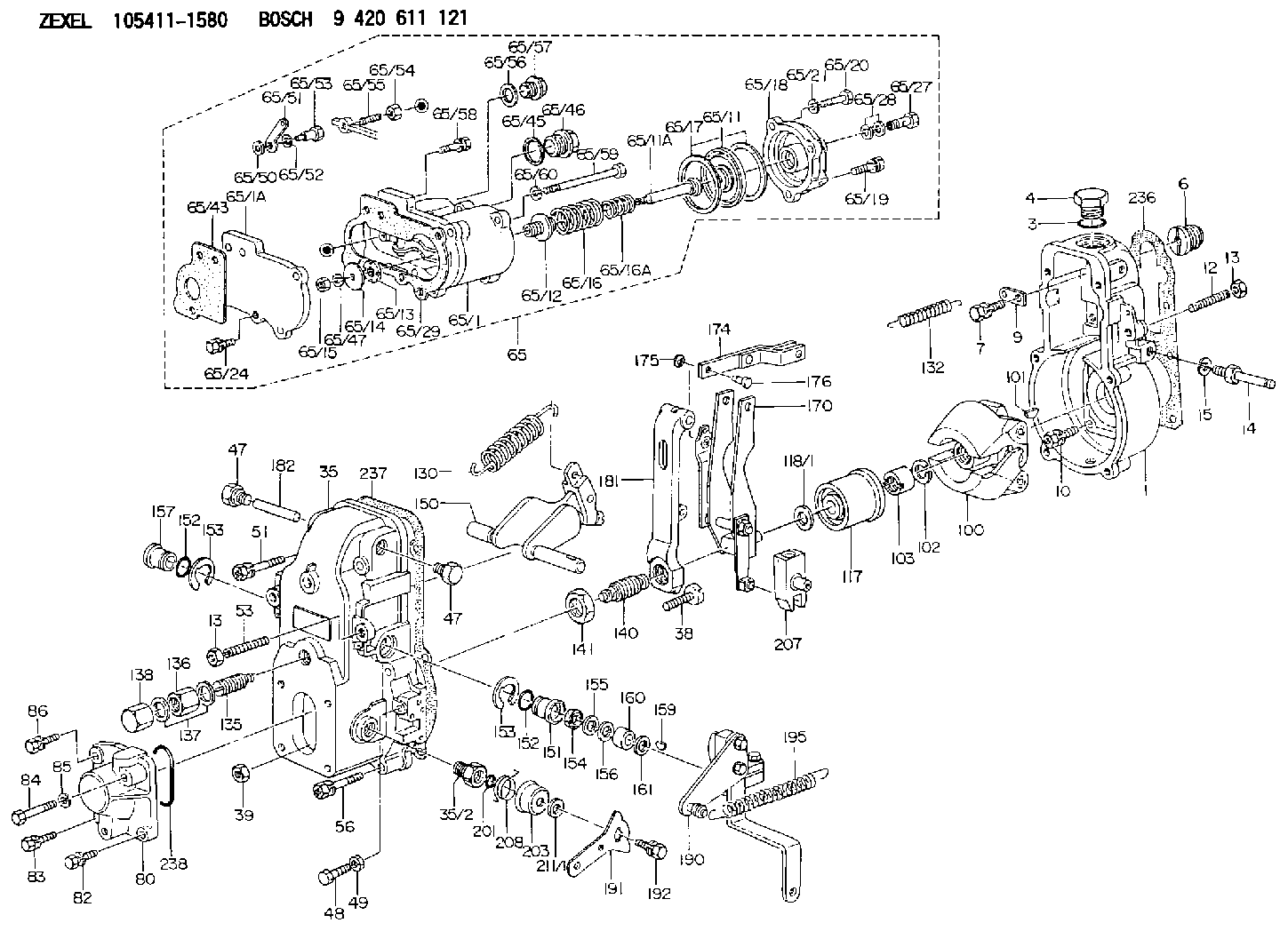
| 1. | [1] | 154000-6400 | GOVERNOR HOUSING |
| 3. | [1] | 029632-5070 | O-RING |
| 4. | [1] | 154007-2900 | CAPSULE |
| 6. | [1] | 154007-0200 | ADAPTOR |
| 7. | [1] | 020018-1840 | BLEEDER SCREW M8P1.25L18 |
| 9. | [1] | 154350-1900 | PLATE |
| 10. | [6] | 029010-6810 | BLEEDER SCREW |
| 12. | [1] | 154010-1100 | FLAT-HEAD SCREW |
| 13. | [2] | 154011-0100 | HEXAGON NUT |
| 13. | [2] | 154011-0100 | HEXAGON NUT |
| 14. | [1] | 154012-2220 | BLEEDER SCREW |
| 15. | [1] | 014110-8440 | LOCKING WASHER |
| 35. | [1] | 154500-3720 | GOVERNOR COVER |
| 35/2. | [1] | 154321-0400 | BUSHING |
| 38. | [1] | 154031-0100 | FLAT-HEAD SCREW |
| 39. | [1] | 013020-6020 | UNION NUT M6P1H5 |
| 47. | [2] | 154036-0300 | CAPSULE |
| 47. | [2] | 154036-0300 | CAPSULE |
| 48. | [1] | 154037-0700 | BLEEDER SCREW |
| 49. | [1] | 154038-0200 | HEXAGON NUT |
| 51. | [2] | 020106-5040 | BLEEDER SCREW |
| 53. | [1] | 154010-0200 | FLAT-HEAD SCREW |
| 56. | [4] | 020106-3840 | BLEEDER SCREW |
| 65. | [1] | 154407-5321 | MANIFOLD-PRESSURE COMP. |
| 65/1. | [1] | 154408-7521 | GOVERNOR HOUSING |
| 65/1A. | [1] | 154408-2801 | SPACER BUSHING |
| 65/11. | [1] | 154400-7020 | DIAPHRAGM |
| 65/11A. | [1] | 154400-6101 | STOP PIN |
| 65/12. | [1] | 154406-5300 | GUIDE SLEEVE |
| 65/13. | [1] | 154406-5400 | UNION NUT |
| 65/14. | [1] | 154406-5500 | SLOTTED WASHER |
| 65/15. | [1] | 013020-6040 | UNION NUT M6P1H5 |
| 65/16. | [1] | 154403-8600 | COILED SPRING |
| 65/16A. | [1] | 154403-7800 | COILED SPRING |
| 65/17. | [2] | 154413-2600 | GASKET |
| 65/18. | [1] | 154404-4920 | COVER |
| 65/19. | [2] | 020106-2040 | BLEEDER SCREW M6P1L20 |
| 65/20. | [1] | 029010-6310 | BLEEDER SCREW |
| 65/21. | [1] | 014110-6440 | LOCKING WASHER |
| 65/24. | [2] | 020106-1640 | BLEEDER SCREW M6P1.0L14 |
| 65/27. | [1] | 029731-0180 | EYE BOLT |
| 65/28. | [2] | 026510-1340 | GASKET D13.4&10.2T1 |
| 65/29. | [1] | 154390-5200 | GASKET |
| 65/43. | [1] | 154390-3400 | GASKET |
| 65/45. | [1] | 029331-8040 | GASKET |
| 65/46. | [1] | 154406-5800 | FLAT-HEAD SCREW |
| 65/47. | [1] | 014110-6440 | LOCKING WASHER |
| 65/50. | [1] | 154406-6200 | SPACER BUSHING |
| 65/51. | [1] | 154406-6300 | CONTROL LEVER |
| 65/52. | [1] | 014110-6440 | LOCKING WASHER |
| 65/53. | [1] | 154406-6400 | BLEEDER SCREW |
| 65/54. | [1] | 013020-6040 | UNION NUT M6P1H5 |
| 65/55. | [1] | 154404-1700 | FLAT-HEAD SCREW L30.00 |
| 65/56. | [1] | 029331-2130 | GASKET |
| 65/57. | [1] | 154406-6500 | FLAT-HEAD SCREW |
| 65/58. | [2] | 020106-2240 | BLEEDER SCREW |
| 65/59. | [2] | 139006-1600 | BLEEDER SCREW |
| 65/60. | [2] | 014110-6440 | LOCKING WASHER |
| 80. | [1] | 154063-0600 | COVER |
| 82. | [1] | 020006-1640 | BLEEDER SCREW M6P1L16 4T |
| 83. | [1] | 020006-1640 | BLEEDER SCREW M6P1L16 4T |
| 84. | [1] | 029020-6250 | BLEEDER SCREW |
| 85. | [1] | 014110-6440 | LOCKING WASHER |
| 86. | [1] | 020006-1640 | BLEEDER SCREW M6P1L16 4T |
| 100. | [1] | 154101-0020 | FLYWEIGHT ASSEMBLY |
| 101. | [1] | 025803-1610 | WOODRUFF KEY |
| 102. | [1] | 029321-2020 | LOCKING WASHER |
| 103. | [1] | 029231-2030 | UNION NUT |
| 117. | [1] | 154123-0120 | SLIDING PIECE |
| 118/1. | [0] | 029311-0010 | SHIM D14&10.1T0.2 |
| 118/1. | [0] | 029311-0180 | SHIM D14&10.1T0.3 |
| 118/1. | [0] | 029311-0190 | SHIM D14&10.1T0.40 |
| 118/1. | [0] | 029311-0210 | SHIM D14&10.1T1 |
| 118/1. | [0] | 139410-0000 | SHIM D14.0&10.1T0.5 |
| 118/1. | [0] | 139410-0100 | SHIM D14.0&10.1T1.5 |
| 118/1. | [0] | 139410-3000 | SHIM D14&10.1T2.0 |
| 118/1. | [0] | 139410-3100 | SHIM D14&10.1T3.0 |
| 118/1. | [0] | 139410-3200 | SHIM D14&10.1T4.0 |
| 130. | [1] | 154150-7700 | GOVERNOR SPRING |
| 132. | [1] | 154154-0800 | COILED SPRING |
| 135. | [1] | 154158-1320 | HEADLESS SCREW |
| 136. | [1] | 154011-2700 | UNION NUT |
| 137. | [2] | 026512-1540 | GASKET D15.4&12.2T1.50 |
| 138. | [1] | 154159-1200 | CAP NUT |
| 140. | [1] | 154177-1220 | HEADLESS SCREW |
| 141. | [1] | 029201-6010 | UNION NUT |
| 150. | [1] | 154200-7220 | SWIVELLING LEVER |
| 151. | [1] | 154204-3000 | BUSHING |
| 152. | [2] | 029631-8020 | O-RING |
| 152. | [2] | 029631-8020 | O-RING |
| 153. | [2] | 016010-1640 | LOCKING WASHER |
| 153. | [2] | 016010-1640 | LOCKING WASHER |
| 154. | [1] | 139611-0000 | PACKING RING |
| 155. | [1] | 139411-0000 | SHIM |
| 156. | [0] | 029311-1070 | SHIM D16&11T0.5 |
| 157. | [1] | 154204-3100 | BUSHING |
| 159. | [1] | 025803-1310 | WOODRUFF KEY |
| 160. | [1] | 154206-2800 | BUSHING |
| 161. | [0] | 154206-0200 | PLAIN WASHER D19.5&11.2T1.0 |
| 170. | [1] | 154210-7420 | FORK LEVER |
| 174. | [1] | 154230-7520 | STRAP |
| 175. | [2] | 016010-0540 | LOCKING WASHER |
| 176. | [1] | 154222-4300 | BEARING PIN |
| 181. | [1] | 154236-1500 | TENSIONING LEVER |
| 182. | [1] | 154237-0100 | BEARING PIN |
| 190. | [1] | 154342-4720 | CONTROL LEVER |
| 191. | [1] | 154307-0100 | CONTROL LEVER |
| 192. | [1] | 020006-1640 | BLEEDER SCREW M6P1L16 4T |
| 195. | [1] | 154314-2600 | COILED SPRING |
| 201. | [1] | 029631-0030 | O-RING &9.8W2.3 |
| 203. | [1] | 154322-0100 | CAP |
| 207. | [1] | 154326-5120 | CONTROL LEVER |
| 208. | [1] | 154327-7300 | COILED SPRING |
| 211/1. | [0] | 029311-0520 | SHIM D20.8&10.3T0.2 |
| 211/1. | [0] | 029311-0530 | SHIM D20.8&10.3T0.25 |
| 211/1. | [0] | 029311-0540 | SHIM D20.8&10.3T0.3 |
| 211/1. | [0] | 029311-0550 | SHIM D20.8&10.3T0.35 |
| 211/1. | [0] | 029311-0560 | SHIM D20.8&10.3T0.4 |
| 211/1. | [0] | 029311-0570 | SHIM D20.8&10.3T0.5 |
| 236. | [1] | 154390-0000 | GASKET |
| 237. | [1] | 154390-0300 | GASKET |
| 238. | [1] | 029635-2020 | O-RING |
Cross reference number
Zexel num
Bosch num
Firm num
Name
105411-1580
1157705720 ISUZU
GOVERNOR
K 14JB MECHANICAL GOVERNOR GOV RSV GOV
K 14JB MECHANICAL GOVERNOR GOV RSV GOV
Information:
Problem
The fuel injector clips may fail on certain 3176 Truck Engines which had injectors replaced after January 1, 1991. A new 6I2538 Clip, made from higher strength material, can be installed to increase the reliability and service life of the injector.
Affected Products
Model & Identification Number
The following 3176 Truck Engines if not previously reworked and stamped with "3X" next to Serial No. Plate.
3176 (2YG1-Up)
Parts Needed
Quantity per injector replaced after January 1, 1991
1 - 6I2538 Clip Add injector(s) and related seal(s) if clip is broken in more than three pieces. Add 336044 O- Ring Seal if thrust pad o-ring is damaged.
Action Required
1. Only certain date code injectors installed as field replacements after January 1, 1991 require c-clip replacement.To determine if any c-clips need reworking requires inspection of the block next to the serial plate, the top surface of the injector spring retainer, and the injector date code.
2. Check for "3X" stamped on the block next to the serial number plate. If the block has been stamped, do not proceed with the rework.3. Inspect the top surface of the injector spring retainer for a red or yellow stripe. The red or yellow indicates that the injector has the latest c-clip and that particular injector requires no further action. Engines equipped with a Jake Brake may require removal of the brake to see the top of the injector clearly.4. Injectors without red or yellow stripes require inspection of the identification label on each fuel injector. The labels can be seen just above the top surface of the valve cover base on the right side of the engine. Record the part number and date code of each injector. Refer to Illustration for the location of the part number and date code on the label. 5. Any injectors without red or yellow stripes that have the following date codes require the c-clips to be reworked.LH, MH, AJ, BJ, CJ, DJ, EJ, or FJ
It may not be possible on many engines to determine the date code from an identification label. the following hints may help in these cases.
A) Only certain part numbers were produced during the specified date code range. All others should be omitted from the rework.If the part number can be read, include the following part numbers if tae date codes are LH, MH, AJ, BJ, CJ, DJ, EJ, or FJ.
4P28104P28204P96104P96200R31770R31780R33990R3400If the part number can be read, omit from this rework the following part numbers (Regardless of date code)
9Y99109Y99207E60107E60207E61107E61200R28330R28340R29800R2981B) Early 9Y9910 and 9Y9920 Injectors did not have identification labels. The part numbers are etched into the solenoid case. Omit these injectors from this rework.C) Early 9Y9910 and 9Y9920 Injectors had six (6) sided wrench flats where the solenoid meets the forged body. If the injector has six (6) sided wrench flats, omit the injector from this rework.D) On early injectors the identification labels were prone to falling off. These were not in the specified date code range and can be omitted from this rework.Examples:
6. If an injector requires rework or replacement, refer to