Information governor
BOSCH
9 420 614 321
9420614321
ZEXEL
105411-1560
1054111560
ISUZU
8970305950
8970305950
Rating:
Scheme ###:
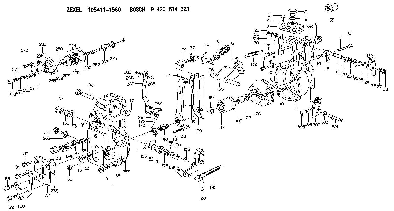
| 1. | [1] | 154004-5620 | GOVERNOR HOUSING |
| 2. | [1] | 154007-2900 | CAPSULE |
| 3. | [1] | 154390-2000 | GASKET |
| 4. | [1] | 154063-7900 | COVER |
| 5. | [4] | 020006-1640 | BLEEDER SCREW M6P1L16 4T |
| 6. | [1] | 154007-0200 | ADAPTOR |
| 7. | [1] | 020018-1840 | BLEEDER SCREW M8P1.25L18 |
| 8. | [1] | 029632-5070 | O-RING |
| 9. | [1] | 154350-1800 | PLATE |
| 10. | [5] | 029010-6810 | BLEEDER SCREW |
| 11. | [1] | 020106-1640 | BLEEDER SCREW M6P1.0L14 |
| 12. | [1] | 154010-0100 | FLAT-HEAD SCREW |
| 13. | [2] | 154011-0100 | HEXAGON NUT |
| 16. | [1] | 155004-3200 | LEVER SHAFT |
| 18. | [1] | 155003-2520 | CONTROL LEVER |
| 19. | [1] | 155006-0100 | BLEEDER SCREW |
| 20. | [1] | 139308-0900 | PLAIN WASHER D16&8T1 |
| 20. | [1] | 139308-0900 | PLAIN WASHER D16&8T1 |
| 20B. | [1] | 139308-1000 | PLAIN WASHER D16&8T1.5 |
| 20B. | [1] | 139308-1000 | PLAIN WASHER D16&8T1.5 |
| 23. | [1] | 025520-1210 | SPLIT PIN |
| 23. | [1] | 025520-1210 | SPLIT PIN |
| 24. | [1] | 154206-2000 | BUSHING |
| 25. | [1] | 154327-4200 | COILED SPRING |
| 26. | [1] | 154366-8700 | CONTROL LEVER |
| 27. | [1] | 014110-8440 | LOCKING WASHER |
| 28. | [1] | 013020-8040 | UNION NUT M8P1.25H7 |
| 30. | [2] | 029620-8050 | PACKING RING |
| 30. | [2] | 029620-8050 | PACKING RING |
| 35. | [1] | 154022-8520 | GOVERNOR COVER |
| 38. | [1] | 154031-0100 | FLAT-HEAD SCREW |
| 39. | [1] | 013020-6020 | UNION NUT M6P1H5 |
| 47. | [1] | 154036-0300 | CAPSULE |
| 51. | [6] | 020106-5040 | BLEEDER SCREW |
| 53. | [1] | 154010-0200 | FLAT-HEAD SCREW |
| 65. | [1] | 155404-0200 | CAP |
| 80. | [1] | 154063-4600 | COVER |
| 82. | [1] | 029020-6260 | BLEEDER SCREW |
| 83. | [1] | 029020-6260 | BLEEDER SCREW |
| 84. | [1] | 020006-2040 | BLEEDER SCREW M6P1L20 4T |
| 86. | [1] | 020006-1640 | BLEEDER SCREW M6P1L16 4T |
| 100. | [1] | 154101-0520 | FLYWEIGHT |
| 101. | [1] | 025803-1610 | WOODRUFF KEY |
| 102. | [1] | 029321-2020 | LOCKING WASHER |
| 103. | [1] | 029231-2030 | UNION NUT |
| 117. | [1] | 154123-2320 | SLIDING PIECE |
| 118/1. | [0] | 029311-0010 | SHIM D14&10.1T0.2 |
| 118/1. | [0] | 029311-0180 | SHIM D14&10.1T0.3 |
| 118/1. | [0] | 029311-0190 | SHIM D14&10.1T0.40 |
| 118/1. | [0] | 029311-0210 | SHIM D14&10.1T1 |
| 118/1. | [0] | 139410-0000 | SHIM D14.0&10.1T0.5 |
| 118/1. | [0] | 139410-0100 | SHIM D14.0&10.1T1.5 |
| 118/1. | [0] | 139410-3000 | SHIM D14&10.1T2.0 |
| 118/1. | [0] | 139410-3100 | SHIM D14&10.1T3.0 |
| 118/1. | [0] | 139410-3200 | SHIM D14&10.1T4.0 |
| 130. | [1] | 154150-2700 | GOVERNOR SPRING |
| 132. | [1] | 154154-0701 | COILED SPRING |
| 135. | [1] | 154158-0820 | HEADLESS SCREW |
| 136. | [1] | 029201-2290 | UNION NUT |
| 137. | [2] | 026512-1540 | GASKET D15.4&12.2T1.50 |
| 138. | [1] | 154159-1200 | CAP NUT |
| 140. | [1] | 154178-9220 | HEADLESS SCREW |
| 141. | [1] | 029201-6010 | UNION NUT |
| 150. | [1] | 154200-7220 | SWIVELLING LEVER |
| 151. | [1] | 154204-3000 | BUSHING |
| 152. | [2] | 029631-8020 | O-RING |
| 152. | [2] | 029631-8020 | O-RING |
| 153. | [2] | 016010-1640 | LOCKING WASHER |
| 153. | [2] | 016010-1640 | LOCKING WASHER |
| 154. | [1] | 139611-0000 | PACKING RING |
| 155. | [1] | 139411-0000 | SHIM |
| 156. | [0] | 029311-1090 | SHIM D16&11T0.3 |
| 157. | [1] | 154204-3100 | BUSHING |
| 159. | [1] | 025803-1310 | WOODRUFF KEY |
| 160. | [1] | 154206-2800 | BUSHING |
| 170. | [1] | 154217-0520 | FORK LEVER |
| 171. | [1] | 016010-0540 | LOCKING WASHER |
| 172. | [4] | 029310-5170 | SHIM D8&5.3T0.5 |
| 173. | [3] | 025520-1210 | SPLIT PIN |
| 174. | [1] | 154234-4020 | STRAP |
| 175. | [1] | 154232-2100 | CONNECTOR |
| 176. | [1] | 154222-5800 | BEARING PIN |
| 177. | [1] | 155402-3800 | SAFETY PIN |
| 181. | [1] | 154236-1500 | TENSIONING LEVER |
| 182. | [1] | 154237-1100 | BEARING PIN |
| 190. | [1] | 154303-5220 | CONTROL LEVER |
| 195. | [1] | 154314-0200 | COILED SPRING |
| 236. | [1] | 154390-1300 | GASKET |
| 237. | [1] | 154390-0300 | GASKET |
| 238. | [1] | 029635-2020 | O-RING |
| 255. | [1] | 154400-7420 | DIAPHRAGM |
| 256. | [1] | 154400-4800 | STOP PIN |
| 257. | [2] | 029330-8050 | GASKET |
| 257. | [2] | 029330-8050 | GASKET |
| 258. | [1] | 139308-0700 | LOCKING WASHER |
| 259. | [1] | 013030-6040 | UNION NUT M6P1H3.6 |
| 260. | [1] | 154401-3720 | CONTROL LEVER |
| 261. | [1] | 154401-1120 | STRAP |
| 262. | [1] | 026510-1440 | GASKET D13.9&10.2T1 |
| 263. | [1] | 154401-2100 | BLEEDER SCREW |
| 264. | [1] | 016010-0540 | LOCKING WASHER |
| 265. | [1] | 154222-6200 | BEARING PIN |
| 266. | [1] | 029300-4010 | PLAIN WASHER |
| 267. | [1] | 154403-3800 | COILED SPRING |
| 268. | [1] | 154404-5000 | COVER |
| 269. | [2] | 020106-2540 | BLEEDER SCREW M6P1L25 |
| 270. | [1] | 154034-1900 | FLAT-HEAD SCREW |
| 271. | [1] | 023040-6040 | UNION NUT |
| 273. | [1] | 029731-0180 | EYE BOLT |
| 274. | [2] | 026510-1340 | GASKET D13.4&10.2T1 |
| 275. | [0] | 029312-0180 | SHIM D25.5&20T0.5 |
| 275B. | [0] | 029312-0210 | SHIM D25.5&20T0.2 |
| 276. | [1] | 154035-0320 | CAP NUT |
| 277. | [1] | 014110-6440 | LOCKING WASHER |
| 278. | [2] | 154413-2600 | GASKET |
| 283. | [1] | 016010-0440 | LOCKING WASHER |
| 285. | [1] | 029010-6310 | BLEEDER SCREW |
| 300. | [1] | 154358-9420 | BRACKET |
| 301. | [1] | 154012-3900 | BLEEDER SCREW |
| 302. | [1] | 014110-8440 | LOCKING WASHER |
| 303. | [1] | 154011-1100 | UNION NUT |
| 304. | [1] | 029300-8320 | SHIM |
| 400. | [1] | 154358-7200 | BRACKET |
Include in #1:
101402-4160
as GOVERNOR
Cross reference number
Zexel num
Bosch num
Firm num
Name
Information:
Parts Needed
6 - 6I2538 Clip Add injectors and related seals if clip is broken in more than three pieces. Add 336044 O-Ring Seal if thrust pad o-ring is damaged.
Action Required
Parts Stock
Remove all of the following injector groups from parts stock. Rework as described in the attached procedure and return to stock.
4P1410 Injector Group4P1420 Injector Group4P2810 Injector Group4P2820 Injector Group4P9510 Injector Group4P9520 Injector Group4P9610 Injector Group4P9620 Injector Group0R3177 Injector Group0R3178 Injector Group0R3400 Injector GroupAffected Product
Rework the injector groups as described in the attached procedure.
Service Claim Allowances
Parts Stock
Submit one claim for all injector groups removed from parts stock and reworked. List the labor to repair each injector on a separate labor line. A maximum of .2 hours labor per fuel injector will be allowed to remove and install the clip.
Affected Product
Parts Disposition
Handle the parts in accordance with your Warranty Bulletin on warranty parts handling.
Attach.
(1-Rework Procedure)Rework Procedure
Parts Stock or Off Engine
Illustration 1 - 9U5300 Unit Injector Spring Compressor Group
Illustration 2 - Compressor Group In Bench Vice
Illustration 3 - Use caution when handling injectors with missing clips. Loose springs and retainers will allow ball to come loose and fall into the engine.1. Remove injectors from packaging and inspect for a paint stripe across the top face of the spring retainer (either yellow or red). The paint stripe indicates the unit injector has been reworked previously. If a clip has failed and the spring/tappet/plunger are loose, use care during injector removal. The plunger retention ball (see Illustration 3) can drop out and fall into the cylinder/engine.
2. Install service tool in a bench vice as shown in Illustration 2 (position to allow for horizontal installation of injector).3. Use an o-ring pick to remove the o-ring from the injector spring retainer. Remove the rocker arm thrust pad.4. Install the injector in the 9U5300 Unit Injector Spring Compressor Group. Tighten the 5P0541 Nut to compress the spring enough to allow removal of the clip (the clip works like a valve keeper).5. Use a small magnet (pencil size works best) and a suitable clip removal tool to remove the oil clip from the injector. Do not release tension on the spring until a new clip is installed. Releasing tension before a new clip is installed will cause the injector will come apart.
6. Injectors removed from engines only. Inspect the clip that was removed. If the clip is broken in more than three (3) pieces (or if you suspect small pieces have fallen into the injector) the unit injector must be replaced.7. Install a new 6I2538 clip and remove injector from spring compressor group.8. Install thrust pad and thrust pad retaining o-ring. If the thrust pad retaining o-ring is damaged install a new 336044 O-Ring Seal.
9. Mark across the top face of the spring retainer with a yellow paint stripe.10. Repackage new parts and mark "3X" on the box.Affected Product
1. Check for 3X stamped on the block next to the serial number plate. If the block has been stamped do not proceed with the rework unless suspect injectors