Information governor
BOSCH
F 019 Z4E 520
f019z4e520
ZEXEL
105411-1220
1054111220
ISUZU
1157209300
1157209300
Rating:
Scheme ###:
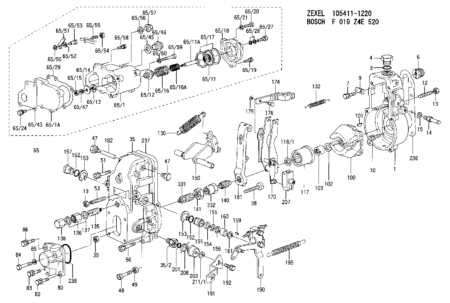
| 1. | [1] | 154000-6400 | GOVERNOR HOUSING |
| 3. | [1] | 029632-5070 | O-RING |
| 4. | [1] | 154007-2900 | CAPSULE |
| 6. | [1] | 154007-0200 | ADAPTOR |
| 7. | [1] | 020018-1840 | BLEEDER SCREW M8P1.25L18 |
| 9. | [1] | 154350-1900 | PLATE |
| 10. | [6] | 029010-6810 | BLEEDER SCREW |
| 12. | [1] | 154010-0100 | FLAT-HEAD SCREW |
| 13. | [2] | 154011-0100 | HEXAGON NUT |
| 13. | [2] | 154011-0100 | HEXAGON NUT |
| 14. | [1] | 154012-1500 | BLEEDER SCREW |
| 15. | [1] | 014110-8440 | LOCKING WASHER |
| 35. | [1] | 154500-3720 | GOVERNOR COVER |
| 35/2. | [1] | 154321-0400 | BUSHING |
| 38. | [1] | 154031-0100 | FLAT-HEAD SCREW |
| 39. | [1] | 013020-6020 | UNION NUT M6P1H5 |
| 47. | [2] | 154036-0300 | CAPSULE |
| 47. | [2] | 154036-0300 | CAPSULE |
| 48. | [1] | 154037-0700 | BLEEDER SCREW |
| 49. | [1] | 154038-0200 | HEXAGON NUT |
| 51. | [2] | 020106-5040 | BLEEDER SCREW |
| 53. | [1] | 154010-0200 | FLAT-HEAD SCREW |
| 56. | [4] | 020106-3840 | BLEEDER SCREW |
| 65. | [1] | 154407-5321 | MANIFOLD-PRESSURE COMP. |
| 65/1. | [1] | 154408-7521 | GOVERNOR HOUSING |
| 65/1A. | [1] | 154408-2801 | SPACER BUSHING |
| 65/11. | [1] | 154400-7020 | DIAPHRAGM |
| 65/11A. | [1] | 154400-6101 | STOP PIN |
| 65/12. | [1] | 154406-5300 | GUIDE SLEEVE |
| 65/13. | [1] | 154406-5400 | UNION NUT |
| 65/14. | [1] | 154406-5500 | SLOTTED WASHER |
| 65/15. | [1] | 013020-6040 | UNION NUT M6P1H5 |
| 65/16. | [1] | 154403-8600 | COILED SPRING |
| 65/16A. | [1] | 154403-7800 | COILED SPRING |
| 65/17. | [2] | 154413-2600 | GASKET |
| 65/18. | [1] | 154404-4920 | COVER |
| 65/19. | [2] | 020106-2040 | BLEEDER SCREW M6P1L20 |
| 65/20. | [1] | 029010-6310 | BLEEDER SCREW |
| 65/21. | [1] | 014110-6440 | LOCKING WASHER |
| 65/24. | [2] | 020106-1640 | BLEEDER SCREW M6P1.0L14 |
| 65/27. | [1] | 029731-0180 | EYE BOLT |
| 65/28. | [2] | 026510-1340 | GASKET D13.4&10.2T1 |
| 65/29. | [1] | 154390-5200 | GASKET |
| 65/43. | [1] | 154390-3400 | GASKET |
| 65/45. | [1] | 029331-8040 | GASKET |
| 65/46. | [1] | 154406-5800 | FLAT-HEAD SCREW |
| 65/47. | [1] | 014110-6440 | LOCKING WASHER |
| 65/50. | [1] | 154406-6200 | SPACER BUSHING |
| 65/51. | [1] | 154406-6300 | CONTROL LEVER |
| 65/52. | [1] | 014110-6440 | LOCKING WASHER |
| 65/53. | [1] | 154406-6400 | BLEEDER SCREW |
| 65/54. | [1] | 013020-6040 | UNION NUT M6P1H5 |
| 65/55. | [1] | 154404-1700 | FLAT-HEAD SCREW L30.00 |
| 65/56. | [1] | 029331-2130 | GASKET |
| 65/57. | [1] | 154406-6500 | FLAT-HEAD SCREW |
| 65/58. | [2] | 020106-2240 | BLEEDER SCREW |
| 65/59. | [2] | 139006-1600 | BLEEDER SCREW |
| 65/60. | [2] | 014110-6440 | LOCKING WASHER |
| 80. | [1] | 154063-0600 | COVER |
| 82. | [1] | 020006-1640 | BLEEDER SCREW M6P1L16 4T |
| 83. | [1] | 020006-1640 | BLEEDER SCREW M6P1L16 4T |
| 84. | [1] | 029020-6250 | BLEEDER SCREW |
| 85. | [1] | 014110-6440 | LOCKING WASHER |
| 86. | [1] | 020006-1640 | BLEEDER SCREW M6P1L16 4T |
| 100. | [1] | 154101-0020 | FLYWEIGHT ASSEMBLY |
| 101. | [1] | 025803-1610 | WOODRUFF KEY |
| 102. | [1] | 029321-2020 | LOCKING WASHER |
| 103. | [1] | 029231-2030 | UNION NUT |
| 117. | [1] | 154123-0120 | SLIDING PIECE |
| 118/1. | [0] | 029311-0010 | SHIM D14&10.1T0.2 |
| 118/1. | [0] | 029311-0180 | SHIM D14&10.1T0.3 |
| 118/1. | [0] | 029311-0190 | SHIM D14&10.1T0.40 |
| 118/1. | [0] | 029311-0210 | SHIM D14&10.1T1 |
| 118/1. | [0] | 139410-0000 | SHIM D14.0&10.1T0.5 |
| 118/1. | [0] | 139410-0100 | SHIM D14.0&10.1T1.5 |
| 118/1. | [0] | 139410-3000 | SHIM D14&10.1T2.0 |
| 118/1. | [0] | 139410-3100 | SHIM D14&10.1T3.0 |
| 118/1. | [0] | 139410-3200 | SHIM D14&10.1T4.0 |
| 130. | [1] | 154150-7700 | GOVERNOR SPRING |
| 132. | [1] | 154154-0800 | COILED SPRING |
| 135. | [1] | 154158-1220 | HEADLESS SCREW |
| 136. | [1] | 154011-2700 | UNION NUT |
| 137. | [2] | 026512-1540 | GASKET D15.4&12.2T1.50 |
| 138. | [1] | 154159-1200 | CAP NUT |
| 140. | [1] | 154178-9220 | HEADLESS SCREW |
| 141. | [1] | 029201-6080 | UNION NUT |
| 150. | [1] | 154200-7220 | SWIVELLING LEVER |
| 151. | [1] | 154204-4300 | BUSHING |
| 152. | [2] | 029631-8020 | O-RING |
| 152. | [2] | 029631-8020 | O-RING |
| 153. | [2] | 016010-1640 | LOCKING WASHER |
| 153. | [2] | 016010-1640 | LOCKING WASHER |
| 154. | [1] | 139611-0000 | PACKING RING |
| 155. | [1] | 139411-0000 | SHIM |
| 156. | [0] | 029311-1070 | SHIM D16&11T0.5 |
| 157. | [1] | 154204-4400 | BUSHING |
| 159. | [1] | 025803-1310 | WOODRUFF KEY |
| 160. | [1] | 154206-2800 | BUSHING |
| 161. | [0] | 154206-0200 | PLAIN WASHER D19.5&11.2T1.0 |
| 170. | [1] | 154210-7420 | FORK LEVER |
| 174. | [1] | 154230-7520 | STRAP |
| 175. | [2] | 016010-0540 | LOCKING WASHER |
| 176. | [1] | 154222-4300 | BEARING PIN |
| 181. | [1] | 154236-1500 | TENSIONING LEVER |
| 182. | [1] | 154237-0100 | BEARING PIN |
| 190. | [1] | 154342-3620 | CONTROL LEVER |
| 191. | [1] | 154304-8900 | CONTROL LEVER |
| 192. | [1] | 020006-1640 | BLEEDER SCREW M6P1L16 4T |
| 195. | [1] | 154314-0200 | COILED SPRING |
| 201. | [1] | 029631-0030 | O-RING &9.8W2.3 |
| 203. | [1] | 154322-0100 | CAP |
| 207. | [1] | 154326-5120 | CONTROL LEVER |
| 208. | [1] | 154327-7300 | COILED SPRING |
| 211/1. | [0] | 029311-0520 | SHIM D20.8&10.3T0.2 |
| 211/1. | [0] | 029311-0530 | SHIM D20.8&10.3T0.25 |
| 211/1. | [0] | 029311-0540 | SHIM D20.8&10.3T0.3 |
| 211/1. | [0] | 029311-0550 | SHIM D20.8&10.3T0.35 |
| 211/1. | [0] | 029311-0560 | SHIM D20.8&10.3T0.4 |
| 211/1. | [0] | 029311-0570 | SHIM D20.8&10.3T0.5 |
| 236. | [1] | 154390-0000 | GASKET |
| 237. | [1] | 154390-0300 | GASKET |
| 238. | [1] | 029635-2020 | O-RING |
| 331. | [1] | 154179-2220 | HEADLESS SCREW |
| 332. | [1] | 029201-6010 | UNION NUT |
Include in #1:
101602-4940
as GOVERNOR
Cross reference number
Zexel num
Bosch num
Firm num
Name
105411-1220
1157209300 ISUZU
GOVERNOR
K 14JB MECHANICAL GOVERNOR GOV RSV GOV
K 14JB MECHANICAL GOVERNOR GOV RSV GOV
Information:
Illustration 4 g01787098
Right side view of machine (A) Hood and guard group (B) Lines group (Air) (C) Air cleaner
Illustration 5 g01787413
Front view of machineInstallation Procedure
Diesel Particulate Filter Installation
Illustration 6 g01787733
(2) 331-8935 Brackets (12) 5P-8245 Hard Washer (13) 6V-8149 Nut (14) 8F-6437 Washer (15) 8T-4956 Bolt
Place two new 331-8935 Brackets (2) parallel to each other on top of the hood. Secure the brackets to the hood using four new 8F-6437 Washers (14), four new 5P-8245 Hard Washers (12), four new 6V-8149 Nuts (13) and four new 8T-4956 Bolts (15). Refer to Illustration 6.
Illustration 7 g01787893
(5) 295-3044 Exhaust Support Gp (Lower half) (14) 8F-6437 Washer (15) 8T-4956 Bolt
Install the two lower halves of the new 295-3044 Exhaust Support Gp (5) onto two brackets (2) using four new 8F-6437 Washers (14) and four new 8T-4956 Bolts (15). Refer to Illustration 7.
Illustration 8 g01788694
(1) 331-8928 Diesel Particulate Filter Gp
Place the new 331-8928 Diesel Particulate Filter Gp (1) onto the two lower halves of exhaust support group (5). The approximate weight of the diesel particulate filter group is 43.6 kg (96.1 lb). Refer to Illustration 8.
Install the two upper halves of exhaust support group (5) onto the lower halves of exhaust support group (5). Secure the two halves of the exhaust support group by using four bolts (5a) and four hard washers (5b). Refer to Illustration 8.
Illustration 9 g01788695
(9) 174-5414 Clamp (11) 255-2899 Tail Pipe As
Connect 255-2899 Tail Pipe As (11) to the outlet module tube of the diesel particulate filter group by using 174-5414 Clamp (9). Refer to Illustration 9.
Illustration 10 g01788698
(3) 331-9162 Filter Tube As (7) 241-6170 Plug (8) 8T-6765 Pipe Plug (10) 209-4589 Clamp
Install the new 331-9162 Filter Tube As (3) to the inlet module tube of the diesel particulate filter group. Secure the connection using one new 209-4589 Clamp (10). Refer to Illustration 10.
Install the new 8T-6765 Pipe Plug (8) and 241-6170 Plug (7) into the respective bosses provided on the filter tube assembly. Refer to Illustration 10.
Illustration 11 g01788714
(6) 270-0112 Bellows
Install the new 270-0112 Bellows (6) to filter tube assembly (3). Secure the connection by using one new Clamp (10). Refer to Illustration 11.
Illustration 12 g01788715
Install the new 331-9161 Filter Tube (4) to bellows (6). Secure the connection by using one new clamp (10). Refer to Illustration 12.
Illustration 13 g01788716
Install the other end of filter tube (4) to the air lines group. Secure the connection by using one new clamp (10). Refer to Illustration 13.Exhaust Monitor Installation
Refer to Special Instruction, REHS5606, "Installation and Operation of the Caterpillar Diesel Particulate Filter (DPF) and the Diagnostic Module for Non-Road Machine Applications (Non-California Applications)" for information regarding the installation and the operation of the exhaust monitor.The exhaust monitor is a device designed to monitor the Caterpillar DPF system continuously. The exhaust monitor provides critical information to the vehicle