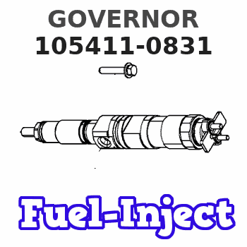
Information governor
BOSCH
F 019 Z9E 662
f019z9e662
ZEXEL
105411-0831
1054110831
Rating:
Scheme ###:
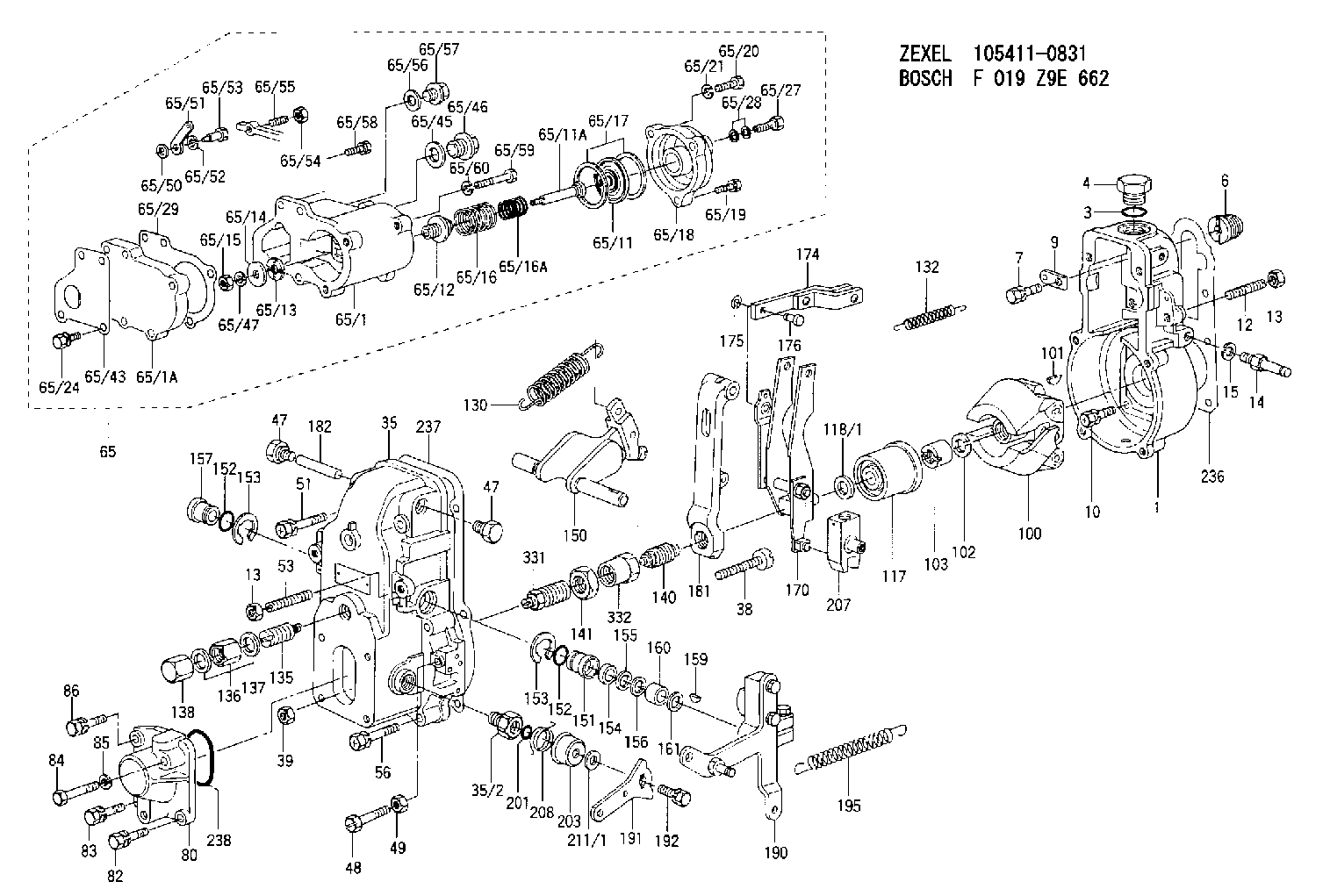
| 1. | [1] | 154000-6400 | GOVERNOR HOUSING |
| 3. | [1] | 029632-5070 | O-RING |
| 4. | [1] | 154007-2900 | CAPSULE |
| 6. | [1] | 154007-0200 | ADAPTOR |
| 7. | [1] | 020018-1840 | BLEEDER SCREW M8P1.25L18 |
| 9. | [1] | 154350-1900 | PLATE |
| 10. | [6] | 029010-6810 | BLEEDER SCREW |
| 12. | [1] | 154010-0100 | FLAT-HEAD SCREW |
| 13. | [2] | 154011-0100 | HEXAGON NUT |
| 13. | [2] | 154011-0100 | HEXAGON NUT |
| 14. | [1] | 154012-1500 | BLEEDER SCREW |
| 15. | [1] | 014110-8440 | LOCKING WASHER |
| 35. | [1] | 154500-3720 | GOVERNOR COVER |
| 35/2. | [1] | 154321-0400 | BUSHING |
| 38. | [1] | 154031-0100 | FLAT-HEAD SCREW |
| 39. | [1] | 013020-6020 | UNION NUT M6P1H5 |
| 47. | [2] | 154036-0300 | CAPSULE |
| 47. | [2] | 154036-0300 | CAPSULE |
| 48. | [1] | 154037-0700 | BLEEDER SCREW |
| 49. | [1] | 154038-0200 | HEXAGON NUT |
| 51. | [2] | 020106-5040 | BLEEDER SCREW |
| 53. | [1] | 154010-0200 | FLAT-HEAD SCREW |
| 56. | [4] | 020106-3840 | BLEEDER SCREW |
| 65. | [1] | 154407-5321 | MANIFOLD-PRESSURE COMP. |
| 65/1. | [1] | 154408-7521 | GOVERNOR HOUSING |
| 65/1A. | [1] | 154408-2801 | SPACER BUSHING |
| 65/11. | [1] | 154400-7020 | DIAPHRAGM |
| 65/11A. | [1] | 154400-6101 | STOP PIN |
| 65/12. | [1] | 154406-5300 | GUIDE SLEEVE |
| 65/13. | [1] | 154406-5400 | UNION NUT |
| 65/14. | [1] | 154406-5500 | SLOTTED WASHER |
| 65/15. | [1] | 013020-6040 | UNION NUT M6P1H5 |
| 65/16. | [1] | 154403-8600 | COILED SPRING |
| 65/16A. | [1] | 154403-7800 | COILED SPRING |
| 65/17. | [2] | 154413-2600 | GASKET |
| 65/18. | [1] | 154404-4920 | COVER |
| 65/19. | [2] | 020106-2040 | BLEEDER SCREW M6P1L20 |
| 65/20. | [1] | 029010-6310 | BLEEDER SCREW |
| 65/21. | [1] | 014110-6440 | LOCKING WASHER |
| 65/24. | [2] | 020106-1640 | BLEEDER SCREW M6P1.0L14 |
| 65/27. | [1] | 029731-0180 | EYE BOLT |
| 65/28. | [2] | 026510-1340 | GASKET D13.4&10.2T1 |
| 65/29. | [1] | 154390-5200 | GASKET |
| 65/43. | [1] | 154390-3400 | GASKET |
| 65/45. | [1] | 029331-8040 | GASKET |
| 65/46. | [1] | 154406-5800 | FLAT-HEAD SCREW |
| 65/47. | [1] | 014110-6440 | LOCKING WASHER |
| 65/50. | [1] | 154406-6200 | SPACER BUSHING |
| 65/51. | [1] | 154406-6300 | CONTROL LEVER |
| 65/52. | [1] | 014110-6440 | LOCKING WASHER |
| 65/53. | [1] | 154406-6400 | BLEEDER SCREW |
| 65/54. | [1] | 013020-6040 | UNION NUT M6P1H5 |
| 65/55. | [1] | 154404-1700 | FLAT-HEAD SCREW L30.00 |
| 65/56. | [1] | 029331-2130 | GASKET |
| 65/57. | [1] | 154406-6500 | FLAT-HEAD SCREW |
| 65/58. | [2] | 020106-2240 | BLEEDER SCREW |
| 65/59. | [2] | 139006-1600 | BLEEDER SCREW |
| 65/60. | [2] | 014110-6440 | LOCKING WASHER |
| 80. | [1] | 154063-0600 | COVER |
| 82. | [1] | 020006-1640 | BLEEDER SCREW M6P1L16 4T |
| 83. | [1] | 020006-1640 | BLEEDER SCREW M6P1L16 4T |
| 84. | [1] | 029020-6250 | BLEEDER SCREW |
| 85. | [1] | 014110-6440 | LOCKING WASHER |
| 86. | [1] | 020006-1640 | BLEEDER SCREW M6P1L16 4T |
| 100. | [1] | 154100-8520 | FLYWEIGHT ASSEMBLY |
| 101. | [1] | 025803-1610 | WOODRUFF KEY |
| 102. | [1] | 029321-2020 | LOCKING WASHER |
| 103. | [1] | 029231-2030 | UNION NUT |
| 117. | [1] | 154123-0120 | SLIDING PIECE |
| 118/1. | [0] | 029311-0010 | SHIM D14&10.1T0.2 |
| 118/1. | [0] | 029311-0180 | SHIM D14&10.1T0.3 |
| 118/1. | [0] | 029311-0190 | SHIM D14&10.1T0.40 |
| 118/1. | [0] | 029311-0210 | SHIM D14&10.1T1 |
| 118/1. | [0] | 139410-0000 | SHIM D14.0&10.1T0.5 |
| 118/1. | [0] | 139410-0100 | SHIM D14.0&10.1T1.5 |
| 118/1. | [0] | 139410-3000 | SHIM D14&10.1T2.0 |
| 118/1. | [0] | 139410-3100 | SHIM D14&10.1T3.0 |
| 118/1. | [0] | 139410-3200 | SHIM D14&10.1T4.0 |
| 130. | [1] | 154150-7700 | GOVERNOR SPRING |
| 132. | [1] | 154154-0800 | COILED SPRING |
| 135. | [1] | 154158-1220 | HEADLESS SCREW |
| 136. | [1] | 154011-2700 | UNION NUT |
| 137. | [2] | 026512-1540 | GASKET D15.4&12.2T1.50 |
| 138. | [1] | 154159-1200 | CAP NUT |
| 140. | [1] | 154178-9220 | HEADLESS SCREW |
| 141. | [1] | 029201-6080 | UNION NUT |
| 150. | [1] | 154200-7220 | SWIVELLING LEVER |
| 151. | [1] | 154204-4300 | BUSHING |
| 152. | [2] | 029631-8020 | O-RING |
| 152. | [2] | 029631-8020 | O-RING |
| 153. | [2] | 016010-1640 | LOCKING WASHER |
| 153. | [2] | 016010-1640 | LOCKING WASHER |
| 154. | [1] | 139611-0000 | PACKING RING |
| 155. | [1] | 139411-0000 | SHIM |
| 156. | [0] | 029311-1070 | SHIM D16&11T0.5 |
| 157. | [1] | 154204-4400 | BUSHING |
| 159. | [1] | 025803-1310 | WOODRUFF KEY |
| 160. | [1] | 154206-2800 | BUSHING |
| 161. | [0] | 154206-0200 | PLAIN WASHER D19.5&11.2T1.0 |
| 170. | [1] | 154210-7420 | FORK LEVER |
| 174. | [1] | 154230-7520 | STRAP |
| 175. | [2] | 016010-0540 | LOCKING WASHER |
| 176. | [1] | 154222-4300 | BEARING PIN |
| 181. | [1] | 154236-1500 | TENSIONING LEVER |
| 182. | [1] | 154237-0100 | BEARING PIN |
| 190. | [1] | 154303-5220 | CONTROL LEVER |
| 191. | [1] | 154307-0100 | CONTROL LEVER |
| 192. | [1] | 020006-1640 | BLEEDER SCREW M6P1L16 4T |
| 195. | [1] | 154314-0200 | COILED SPRING |
| 201. | [1] | 029631-0030 | O-RING &9.8W2.3 |
| 203. | [1] | 154322-0100 | CAP |
| 207. | [1] | 154326-5120 | CONTROL LEVER |
| 208. | [1] | 154327-7300 | COILED SPRING |
| 211/1. | [0] | 029311-0520 | SHIM D20.8&10.3T0.2 |
| 211/1. | [0] | 029311-0530 | SHIM D20.8&10.3T0.25 |
| 211/1. | [0] | 029311-0540 | SHIM D20.8&10.3T0.3 |
| 211/1. | [0] | 029311-0550 | SHIM D20.8&10.3T0.35 |
| 211/1. | [0] | 029311-0560 | SHIM D20.8&10.3T0.4 |
| 211/1. | [0] | 029311-0570 | SHIM D20.8&10.3T0.5 |
| 236. | [1] | 154390-0000 | GASKET |
| 237. | [1] | 154390-0300 | GASKET |
| 238. | [1] | 029635-2020 | O-RING |
| 331. | [1] | 154179-2220 | HEADLESS SCREW |
| 332. | [1] | 029201-6010 | UNION NUT |
Include in #1:
101602-4070
as GOVERNOR
Cross reference number
Zexel num
Bosch num
Firm num
Name
105411-0831
F 019 Z9E 662
GOVERNOR
* K 14JB GOV RSV GOV
* K 14JB GOV RSV GOV
Information:
Illustration 23. (2) 141-6737 Adjustable Microgauge.
(7) Top of the 3P-1542 Barrel. (8) 141-6727 Calibration Pump Assembly.1. Place the 141-6737 Adjustable Microgauge on top of the 3P-1542 Barrel of the 141-6727 Calibration Pump Assembly.2. When starting to torque 124-5932 Lever Assemblies, the difference between the face of the 141-6730 Plunger and the 2N-2658 Bolt is about 0.03 mm (.001 in). By setting the 141-6737 Adjustable Microgauge (2) on top of the 141-6727 Calibration Pump Assembly (8), the 141-6737 Plunger can be positioned 25.40 mm (.001 in) above the face of the 3P-1542 Barrel (7).
Illustration 24. (9) 2N-2658 Bolt. (10) 124-5940 Shutoff Lever.3. As the 2N-2658 Bolt (9) is torqued, the 141-6730 Plunger will move down flush with the 3P-1542 Barrel (7) or will be very close to being flush. The calibration can begin from this point. The 2N-2658 Bolts must freely turn in and out of the 124-5940 Shutoff Levers (10) because the calibration depends on where the head of the 2N-2658 Bolt (9) first begins to clamp the 124-5940 Shutoff Lever for the starting point of the calibration.End Play Adjustment
1. In order to save time, use two torque wrenches (color-coding is convenient for distinguishing between the two wrenches). Set one torque wrench to 1.7 N m (15 lb in) and the second torque wrench to N m (35 lb in).
Illustration 25. (1) 124-5941 Shaft. (2) 4N-1826 Dowel on one end of the HSMFS Injection Pump Group. (3) 126-7232 Dowels.2. Adjust the end play in the 124-5941 Shaft. The SMFS 109-0324 Governor And Fuel Injection Pump Group had the dowel in the middle of the sleeve and a large amount of end play in the shaft was acceptable. Now that the 126-7232 Dowels (3) are between two 124-5934 Sleeves, the amount of end play is important. It is necessary that an adjustment be performed to minimize the amount of end play in the 124-5941 Shaft (1).3. The 126-7232 Dowels (3) are located between two 124-5934 Sleeves. Set the 126-7232 Dowels between 0.25 to 0.40 mm (.010 to .016 in) by tapping in the 4N-1826 Dowels (2) until the desired end play is achieved.* With the 1.7 N m (15 lb in) torque wrench, torque the 2N-2658 Bolts to 1.7 N m (15 lb in).* Then use the 4 N m (35 lb in) torque wrench to torque the 2N-2658 Bolts to 3.4 N m (30 lb in) in order to calibrate within specifications.Calibrating the 124-5932 Lever Assemblies.
Illustration 26. Calibrating the 124-5932 Lever Assemblies.
(1) 2N-2658 Bolts. (2) 124-5940 Shutoff Lever.1. Begin with the first 2N-2658 Bolt (1) and turn it until it just begins to clamp (feels snug) on the 124-5940 Shutoff Lever (2).2. Move to the other side and turn the second 2N-2658 Bolt (1) until just begins to clamp (feels snug).* Alternate between sides and tighten each 2N-2658 Bolt about 15 degrees each time.
Illustration 27. View of the HSMFS Injection Pump Group.
(3) Top of the 141-6730 Plunger shown flush with the 3P-1542 Barrel (4).3. Continue until the torque
Have questions with 105411-0831?
Group cross 105411-0831 ZEXEL
Isuzu
Isuzu
Isuzu
105411-0831
F 019 Z9E 662
GOVERNOR