Information governor
BOSCH
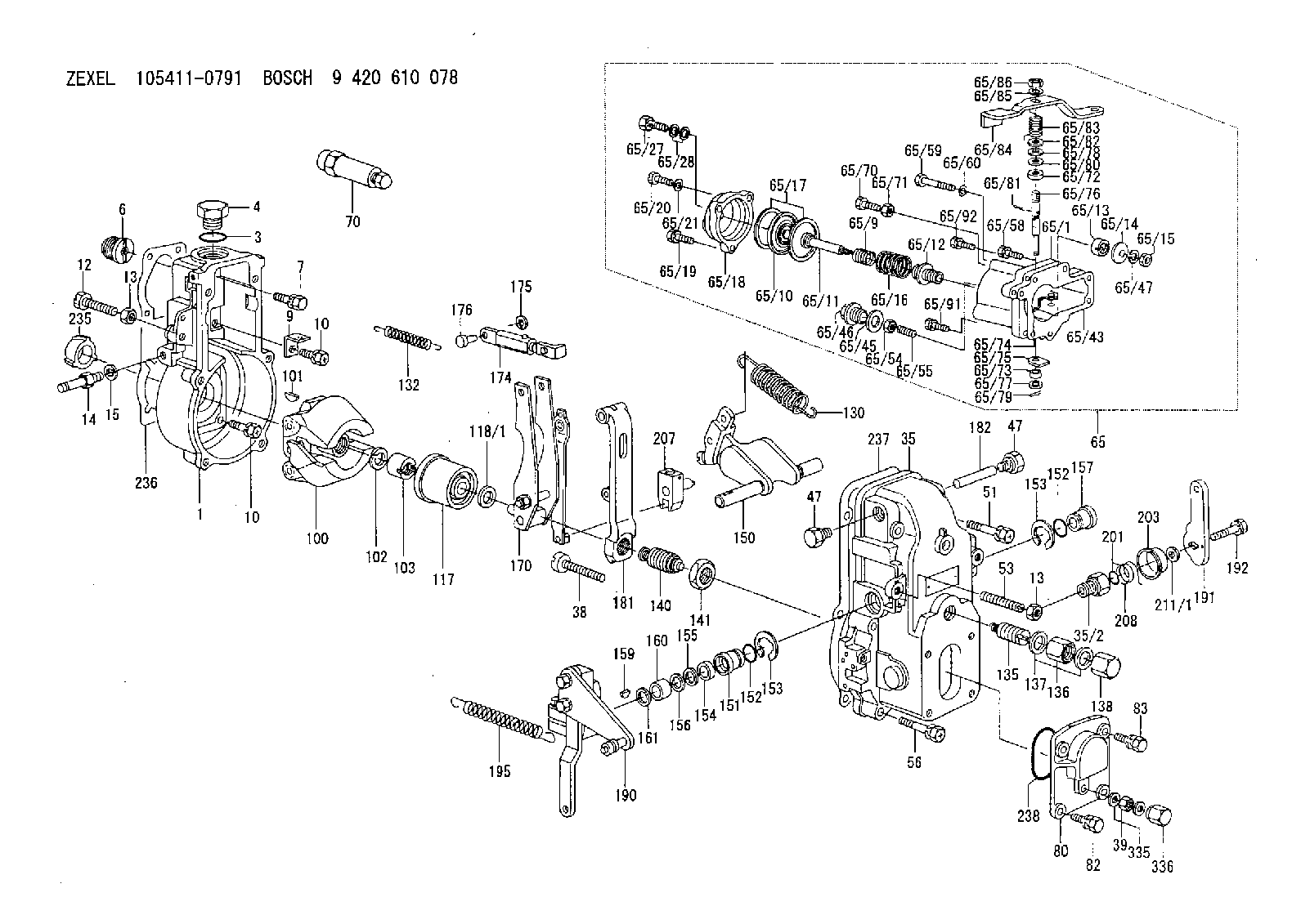
9 420 610 078
9420610078
ZEXEL
105411-0791
1054110791
Rating:
Scheme ###:
| 1. | [1] | 154000-7000 | GOVERNOR HOUSING |
| 3. | [1] | 029632-5070 | O-RING |
| 4. | [1] | 154007-2900 | CAPSULE |
| 6. | [1] | 154007-0200 | ADAPTOR |
| 7. | [1] | 020018-1840 | BLEEDER SCREW M8P1.25L18 |
| 9. | [1] | 154350-1900 | PLATE |
| 10. | [6] | 029010-6810 | BLEEDER SCREW |
| 10. | [6] | 029010-6810 | BLEEDER SCREW |
| 12. | [1] | 154010-4300 | BLEEDER SCREW |
| 13. | [2] | 154011-0100 | HEXAGON NUT |
| 13. | [2] | 154011-0100 | HEXAGON NUT |
| 14. | [1] | 154012-3320 | BLEEDER SCREW |
| 15. | [1] | 014110-8440 | LOCKING WASHER |
| 35. | [1] | 154500-3020 | GOVERNOR COVER |
| 35/2. | [1] | 154321-0400 | BUSHING |
| 38. | [1] | 154031-2400 | FLAT-HEAD SCREW |
| 39. | [1] | 139206-0600 | UNION NUT |
| 47. | [2] | 154036-0300 | CAPSULE |
| 47. | [2] | 154036-0300 | CAPSULE |
| 51. | [2] | 020106-5040 | BLEEDER SCREW |
| 53. | [1] | 154010-0100 | FLAT-HEAD SCREW |
| 56. | [4] | 020106-3840 | BLEEDER SCREW |
| 65. | [1] | 154407-6121 | MANIFOLD-PRESSURE COMP. |
| 65/1. | [1] | 154408-8720 | DIAPHRAGM HOUSING |
| 65/9. | [1] | 154403-9700 | COILED SPRING |
| 65/10. | [1] | 154400-7520 | DIAPHRAGM |
| 65/11. | [1] | 154400-6101 | STOP PIN |
| 65/12. | [1] | 154406-5300 | GUIDE SLEEVE |
| 65/13. | [1] | 154406-5400 | UNION NUT |
| 65/14. | [1] | 154406-5500 | SLOTTED WASHER |
| 65/15. | [1] | 013020-6040 | UNION NUT M6P1H5 |
| 65/16. | [1] | 154403-9800 | COILED SPRING |
| 65/17. | [2] | 154413-2600 | GASKET |
| 65/18. | [1] | 154404-4920 | COVER |
| 65/19. | [2] | 020106-2040 | BLEEDER SCREW M6P1L20 |
| 65/20. | [1] | 029010-6310 | BLEEDER SCREW |
| 65/21. | [1] | 014110-6440 | LOCKING WASHER |
| 65/27. | [1] | 029731-0180 | EYE BOLT |
| 65/28. | [2] | 026510-1340 | GASKET D13.4&10.2T1 |
| 65/43. | [1] | 154406-6600 | GASKET |
| 65/45. | [1] | 029331-8040 | GASKET |
| 65/46. | [1] | 154406-5800 | FLAT-HEAD SCREW |
| 65/47. | [1] | 014110-6440 | LOCKING WASHER |
| 65/54. | [1] | 013020-6040 | UNION NUT M6P1H5 |
| 65/55. | [1] | 154404-1500 | FLAT-HEAD SCREW L22.00 |
| 65/58. | [2] | 020106-1840 | BLEEDER SCREW M6P1L18 |
| 65/59. | [2] | 010006-6540 | BLEEDER SCREW M6P1L65 4T |
| 65/60. | [2] | 014110-6440 | LOCKING WASHER |
| 65/70. | [1] | 029030-6020 | BLEEDER SCREW M6P1.0L18 |
| 65/71. | [1] | 029240-6010 | UNION NUT M6P1.0H5* |
| 65/72. | [1] | 139608-0000 | PACKING RING |
| 65/73. | [1] | 139605-0100 | PACKING RING |
| 65/74. | [1] | 154408-8800 | CONTROL LEVER |
| 65/75. | [1] | 154406-7500 | CONTROL LEVER |
| 65/76. | [1] | 154406-7600 | LEVER SHAFT |
| 65/77. | [1] | 029310-5200 | SHIM |
| 65/78. | [1] | 014020-8120 | PLAIN WASHER D16&8.5T1.2 |
| 65/79. | [1] | 154372-6500 | SAFETY PIN |
| 65/80. | [0] | 029310-8040 | SHIM D13.5&8T0.2 |
| 65/80B. | [0] | 029310-8050 | SHIM D13.5&8T0.5 |
| 65/81. | [1] | 025520-1210 | SPLIT PIN |
| 65/82. | [2] | 029300-8320 | SHIM |
| 65/83. | [1] | 154403-9900 | COILED SPRING |
| 65/84. | [1] | 154406-7700 | CONTROL LEVER |
| 65/85. | [1] | 014110-8440 | LOCKING WASHER |
| 65/86. | [1] | 013020-8140 | UNION NUT M8P1.25H6.5 |
| 65/91. | [1] | 029010-6590 | BLEEDER SCREW |
| 65/92. | [1] | 020006-1840 | BLEEDER SCREW M6P1L18 |
| 70. | [1] | 153020-3620 | STOPPING DEVICE |
| 80. | [1] | 154063-1400 | COVER |
| 82. | [2] | 029020-6210 | BLEEDER SCREW |
| 83. | [2] | 020006-1640 | BLEEDER SCREW M6P1L16 4T |
| 100. | [1] | 154101-0020 | FLYWEIGHT ASSEMBLY |
| 101. | [1] | 025803-1610 | WOODRUFF KEY |
| 102. | [1] | 029321-2020 | LOCKING WASHER |
| 103. | [1] | 029231-2030 | UNION NUT |
| 117. | [1] | 154123-0120 | SLIDING PIECE |
| 118/1. | [0] | 029311-0010 | SHIM D14&10.1T0.2 |
| 118/1. | [0] | 029311-0180 | SHIM D14&10.1T0.3 |
| 118/1. | [0] | 029311-0190 | SHIM D14&10.1T0.40 |
| 118/1. | [0] | 029311-0210 | SHIM D14&10.1T1 |
| 118/1. | [0] | 139410-0000 | SHIM D14.0&10.1T0.5 |
| 118/1. | [0] | 139410-0100 | SHIM D14.0&10.1T1.5 |
| 118/1. | [0] | 139410-3000 | SHIM D14&10.1T2.0 |
| 118/1. | [0] | 139410-3100 | SHIM D14&10.1T3.0 |
| 118/1. | [0] | 139410-3200 | SHIM D14&10.1T4.0 |
| 130. | [1] | 154150-2900 | GOVERNOR SPRING |
| 132. | [1] | 154154-0701 | COILED SPRING |
| 135. | [1] | 154158-2320 | HEADLESS SCREW |
| 136. | [1] | 154011-2700 | UNION NUT |
| 137. | [2] | 026512-1540 | GASKET D15.4&12.2T1.50 |
| 138. | [1] | 154159-1200 | CAP NUT |
| 140. | [1] | 154185-2120 | HEADLESS SCREW |
| 141. | [1] | 029201-6010 | UNION NUT |
| 150. | [1] | 154200-7020 | SWIVELLING LEVER |
| 151. | [1] | 154204-4300 | BUSHING |
| 152. | [2] | 029631-8020 | O-RING |
| 152. | [2] | 029631-8020 | O-RING |
| 153. | [2] | 016010-1640 | LOCKING WASHER |
| 153. | [2] | 016010-1640 | LOCKING WASHER |
| 154. | [1] | 139611-0000 | PACKING RING |
| 155. | [1] | 139411-0000 | SHIM |
| 156. | [0] | 029311-1070 | SHIM D16&11T0.5 |
| 157. | [1] | 154204-4400 | BUSHING |
| 159. | [1] | 025803-1310 | WOODRUFF KEY |
| 160. | [1] | 154206-2800 | BUSHING |
| 161. | [0] | 154206-0200 | PLAIN WASHER D19.5&11.2T1.0 |
| 170. | [1] | 154210-7420 | FORK LEVER |
| 174. | [1] | 154230-8320 | STRAP |
| 175. | [2] | 016010-0540 | LOCKING WASHER |
| 176. | [1] | 154222-4300 | BEARING PIN |
| 181. | [1] | 154236-4100 | TENSIONING LEVER |
| 182. | [1] | 154237-0100 | BEARING PIN |
| 190. | [1] | 154345-7920 | CONTROL LEVER |
| 191. | [1] | 154364-0900 | CONTROL LEVER |
| 192. | [1] | 020006-1640 | BLEEDER SCREW M6P1L16 4T |
| 195. | [1] | 154314-2500 | COILED SPRING |
| 201. | [1] | 029631-0030 | O-RING &9.8W2.3 |
| 203. | [1] | 154322-0100 | CAP |
| 207. | [1] | 154326-5120 | CONTROL LEVER |
| 208. | [1] | 154327-7300 | COILED SPRING |
| 211/1. | [0] | 029311-0520 | SHIM D20.8&10.3T0.2 |
| 211/1. | [0] | 029311-0530 | SHIM D20.8&10.3T0.25 |
| 211/1. | [0] | 029311-0540 | SHIM D20.8&10.3T0.3 |
| 211/1. | [0] | 029311-0550 | SHIM D20.8&10.3T0.35 |
| 211/1. | [0] | 029311-0560 | SHIM D20.8&10.3T0.4 |
| 211/1. | [0] | 029311-0570 | SHIM D20.8&10.3T0.5 |
| 235. | [1] | 155412-5200 | IMPELLER WHEEL |
| 236. | [1] | 154390-0000 | GASKET |
| 237. | [1] | 154390-0300 | GASKET |
| 238. | [1] | 029635-2020 | O-RING |
| 335. | [2] | 026506-1040 | GASKET D9.9&6.2T1 |
| 336. | [1] | 154035-1600 | CAP NUT |
Cross reference number
Zexel num
Bosch num
Firm num
Name
105411-0791
GOVERNOR
K 14JB MECHANICAL GOVERNOR GOV RSV GOV
K 14JB MECHANICAL GOVERNOR GOV RSV GOV
Information:
2. Disconnect the fuel injection lines (2) from pump housing. Put plugs or caps in all lines and openings.3. Remove the three bolts that hold the fuel filter (3) to the aftercooler housing.4. Disconnect the sensing line (1) for the fuel ratio control from the aftercooler housing. 5. Disconnect the oil supply line (4) from the turbocharger.6. Remove the two water lines (5). 7. Disconnect the water outlet line (6) for the air compressor from the cylinder head.8. Remove the bolts (7) that fasten the cylinder head to the cylinder block. 9. Install 3/8"-16NC forged eyebolts in the cylinder head. Fasten a hoist and remove the cylinder head assembly. Weight of cylinder head assembly is 575 lb. (260 kg). Be sure to install a new gasket between the spacer plate and the cylinder block before installing the cylinder head assembly. See REMOVE and INSTALL SPACER PLATE in DISASSEMBLY AND ASSEMBLY.Install Cylinder Head Assembly
1. Clean the top surface of spacer plate and the surface it is in contact with on the cylinder head.2. Install the cylinder head gasket, water seals, and gasket on timing gear cover. 3. Install the 3/8"-16NC forged eyebolts in the cylinder head. Fasten a hoist and put the cylinder head assembly into position on the engine. Make sure the gear (1) in cylinder head is engaged with drive gear (2). 4. Put 9M3710 Anti-Seize Compound on the threads of the bolts for cylinder head. Install the bolts and washers. Tighten the bolts as follows: 1 -Tighten all bolts in number order to 135 lb.ft. (18.7 mkg).2 -Tighten all bolts in number order to 185 5 lb.ft. (25.6 0.7 mkg).3 -Tighten all bolts using hand torque only to 185 5 lb.ft. (25.6 0.7 mkg). 5. Install the two water lines (4).6. Connect the oil supply line (3) to the turbocharger.7. Connect the water outlet line (5) for the air compressor to the cylinder head. 8. Connect the sensing line (6) for the fuel ratio control to the aftercooler housing.9. Put the fuel filter in position, and install the three bolts.10. Remove the plugs and fuel injection lines and pumps. Connect the fuel injection lines (7) to the pumps. Tighten the nuts on fuel lines to 30 5 lb.ft. (4.1 0.7 mkg).11. Fill the cooling system with coolant.end by: a) install camshaft housingb) install fan drive
1. Clean the top surface of spacer plate and the surface it is in contact with on the cylinder head.2. Install the cylinder head gasket, water seals, and gasket on timing gear cover. 3. Install the 3/8"-16NC forged eyebolts in the cylinder head. Fasten a hoist and put the cylinder head assembly into position on the engine. Make sure the gear (1) in cylinder head is engaged with drive gear (2). 4. Put 9M3710 Anti-Seize Compound on the threads of the bolts for cylinder head. Install the bolts and washers. Tighten the bolts as follows: 1 -Tighten all bolts in number order to 135 lb.ft. (18.7 mkg).2 -Tighten all bolts in number order to 185 5 lb.ft. (25.6 0.7 mkg).3 -Tighten all bolts using hand torque only to 185 5 lb.ft. (25.6 0.7 mkg). 5. Install the two water lines (4).6. Connect the oil supply line (3) to the turbocharger.7. Connect the water outlet line (5) for the air compressor to the cylinder head. 8. Connect the sensing line (6) for the fuel ratio control to the aftercooler housing.9. Put the fuel filter in position, and install the three bolts.10. Remove the plugs and fuel injection lines and pumps. Connect the fuel injection lines (7) to the pumps. Tighten the nuts on fuel lines to 30 5 lb.ft. (4.1 0.7 mkg).11. Fill the cooling system with coolant.end by: a) install camshaft housingb) install fan drive