Information governor
BOSCH
F 019 Z1E 139
f019z1e139
ZEXEL
105411-0751
1054110751
ISUZU
1157205580
1157205580
Rating:
Scheme ###:
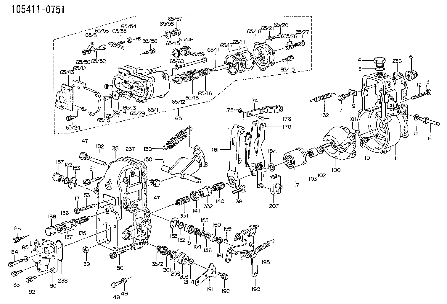
| 1. | [1] | 154000-6400 | GOVERNOR HOUSING |
| 3. | [1] | 029632-5070 | O-RING |
| 4. | [1] | 154007-2900 | CAPSULE |
| 6. | [1] | 154007-0200 | ADAPTOR |
| 7. | [1] | 020018-1840 | BLEEDER SCREW M8P1.25L18 |
| 9. | [1] | 154350-1900 | PLATE |
| 10. | [6] | 029010-6810 | BLEEDER SCREW |
| 12. | [1] | 154010-0100 | FLAT-HEAD SCREW |
| 13. | [2] | 154011-0100 | HEXAGON NUT |
| 13. | [2] | 154011-0100 | HEXAGON NUT |
| 14. | [1] | 154012-1500 | BLEEDER SCREW |
| 15. | [1] | 014110-8440 | LOCKING WASHER |
| 35. | [1] | 154500-3720 | GOVERNOR COVER |
| 35/2. | [1] | 154321-0400 | BUSHING |
| 38. | [1] | 154031-0100 | FLAT-HEAD SCREW |
| 39. | [1] | 013020-6020 | UNION NUT M6P1H5 |
| 47. | [2] | 154036-0300 | CAPSULE |
| 47. | [2] | 154036-0300 | CAPSULE |
| 48. | [1] | 154037-0700 | BLEEDER SCREW |
| 49. | [1] | 154038-0200 | HEXAGON NUT |
| 51. | [2] | 020106-5040 | BLEEDER SCREW |
| 53. | [1] | 154010-0200 | FLAT-HEAD SCREW |
| 56. | [4] | 020106-3840 | BLEEDER SCREW |
| 65. | [1] | 154407-5321 | MANIFOLD-PRESSURE COMP. |
| 65/1. | [1] | 154408-7521 | GOVERNOR HOUSING |
| 65/1A. | [1] | 154408-2801 | SPACER BUSHING |
| 65/11. | [1] | 154400-7020 | DIAPHRAGM |
| 65/11. | [1] | 154400-7020 | DIAPHRAGM |
| 65/11A. | [1] | 154400-6101 | STOP PIN |
| 65/12. | [1] | 154406-5300 | GUIDE SLEEVE |
| 65/13. | [1] | 154406-5400 | UNION NUT |
| 65/14. | [1] | 154406-5500 | SLOTTED WASHER |
| 65/15. | [1] | 013020-6040 | UNION NUT M6P1H5 |
| 65/16. | [1] | 154403-8600 | COILED SPRING |
| 65/16. | [1] | 154403-8600 | COILED SPRING |
| 65/16A. | [1] | 154403-7800 | COILED SPRING |
| 65/17. | [2] | 154413-2600 | GASKET |
| 65/18. | [1] | 154404-4920 | COVER |
| 65/19. | [2] | 020106-2040 | BLEEDER SCREW M6P1L20 |
| 65/20. | [1] | 029010-6310 | BLEEDER SCREW |
| 65/21. | [1] | 014110-6440 | LOCKING WASHER |
| 65/24. | [2] | 020106-1640 | BLEEDER SCREW M6P1.0L14 |
| 65/27. | [1] | 029731-0180 | EYE BOLT |
| 65/28. | [2] | 026510-1340 | GASKET D13.4&10.2T1 |
| 65/29. | [1] | 154390-5200 | GASKET |
| 65/43. | [1] | 154390-3400 | GASKET |
| 65/45. | [1] | 029331-8040 | GASKET |
| 65/46. | [1] | 154406-5800 | FLAT-HEAD SCREW |
| 65/47. | [1] | 014110-6440 | LOCKING WASHER |
| 65/50. | [1] | 154406-6200 | SPACER BUSHING |
| 65/51. | [1] | 154406-6300 | CONTROL LEVER |
| 65/52. | [1] | 014110-6440 | LOCKING WASHER |
| 65/53. | [1] | 154406-6400 | BLEEDER SCREW |
| 65/54. | [1] | 013020-6040 | UNION NUT M6P1H5 |
| 65/55. | [1] | 154404-1700 | FLAT-HEAD SCREW L30.00 |
| 65/56. | [1] | 029331-2130 | GASKET |
| 65/57. | [1] | 154406-6500 | FLAT-HEAD SCREW |
| 65/58. | [2] | 020106-2240 | BLEEDER SCREW |
| 65/59. | [2] | 139006-1600 | BLEEDER SCREW |
| 65/60. | [2] | 014110-6440 | LOCKING WASHER |
| 80. | [1] | 154063-0600 | COVER |
| 82. | [1] | 020006-1640 | BLEEDER SCREW M6P1L16 4T |
| 83. | [1] | 020006-1640 | BLEEDER SCREW M6P1L16 4T |
| 84. | [1] | 029020-6250 | BLEEDER SCREW |
| 85. | [1] | 014110-6440 | LOCKING WASHER |
| 86. | [1] | 020006-1640 | BLEEDER SCREW M6P1L16 4T |
| 100. | [1] | 154101-0020 | FLYWEIGHT ASSEMBLY |
| 101. | [1] | 025803-1610 | WOODRUFF KEY |
| 102. | [1] | 029321-2020 | LOCKING WASHER |
| 103. | [1] | 029231-2030 | UNION NUT |
| 117. | [1] | 154123-0120 | SLIDING PIECE |
| 118/1. | [0] | 029311-0010 | SHIM D14&10.1T0.2 |
| 118/1. | [0] | 029311-0180 | SHIM D14&10.1T0.3 |
| 118/1. | [0] | 029311-0190 | SHIM D14&10.1T0.40 |
| 118/1. | [0] | 029311-0210 | SHIM D14&10.1T1 |
| 118/1. | [0] | 139410-0000 | SHIM D14.0&10.1T0.5 |
| 118/1. | [0] | 139410-0100 | SHIM D14.0&10.1T1.5 |
| 118/1. | [0] | 139410-3000 | SHIM D14&10.1T2.0 |
| 118/1. | [0] | 139410-3100 | SHIM D14&10.1T3.0 |
| 118/1. | [0] | 139410-3200 | SHIM D14&10.1T4.0 |
| 130. | [1] | 154150-7700 | GOVERNOR SPRING |
| 132. | [1] | 154154-0800 | COILED SPRING |
| 135. | [1] | 154158-1220 | HEADLESS SCREW |
| 136. | [1] | 154011-2700 | UNION NUT |
| 137. | [2] | 026512-1540 | GASKET D15.4&12.2T1.50 |
| 138. | [1] | 154159-1200 | CAP NUT |
| 140. | [1] | 154178-9220 | HEADLESS SCREW |
| 141. | [1] | 029201-6080 | UNION NUT |
| 150. | [1] | 154200-7220 | SWIVELLING LEVER |
| 151. | [1] | 154204-4300 | BUSHING |
| 152. | [2] | 029631-8020 | O-RING |
| 152. | [2] | 029631-8020 | O-RING |
| 153. | [2] | 016010-1640 | LOCKING WASHER |
| 153. | [2] | 016010-1640 | LOCKING WASHER |
| 154. | [1] | 139611-0000 | PACKING RING |
| 155. | [1] | 139411-0000 | SHIM |
| 156. | [0] | 029311-1070 | SHIM D16&11T0.5 |
| 157. | [1] | 154204-4400 | BUSHING |
| 159. | [1] | 025803-1310 | WOODRUFF KEY |
| 160. | [1] | 154206-2800 | BUSHING |
| 161. | [0] | 154206-0200 | PLAIN WASHER D19.5&11.2T1.0 |
| 170. | [1] | 154210-7420 | FORK LEVER |
| 174. | [1] | 154230-7520 | STRAP |
| 175. | [2] | 016010-0540 | LOCKING WASHER |
| 176. | [1] | 154222-4300 | BEARING PIN |
| 181. | [1] | 154236-1500 | TENSIONING LEVER |
| 182. | [1] | 154237-0100 | BEARING PIN |
| 190. | [1] | 154342-3620 | CONTROL LEVER |
| 191. | [1] | 154307-0100 | CONTROL LEVER |
| 192. | [1] | 020006-1640 | BLEEDER SCREW M6P1L16 4T |
| 195. | [1] | 154314-0200 | COILED SPRING |
| 201. | [1] | 029631-0030 | O-RING &9.8W2.3 |
| 203. | [1] | 154322-0100 | CAP |
| 207. | [1] | 154326-5120 | CONTROL LEVER |
| 208. | [1] | 154327-7300 | COILED SPRING |
| 211/1. | [0] | 029311-0520 | SHIM D20.8&10.3T0.2 |
| 211/1. | [0] | 029311-0530 | SHIM D20.8&10.3T0.25 |
| 211/1. | [0] | 029311-0540 | SHIM D20.8&10.3T0.3 |
| 211/1. | [0] | 029311-0550 | SHIM D20.8&10.3T0.35 |
| 211/1. | [0] | 029311-0560 | SHIM D20.8&10.3T0.4 |
| 211/1. | [0] | 029311-0570 | SHIM D20.8&10.3T0.5 |
| 236. | [1] | 154390-0000 | GASKET |
| 237. | [1] | 154390-0300 | GASKET |
| 238. | [1] | 029635-2020 | O-RING |
| 331. | [1] | 154179-2220 | HEADLESS SCREW |
| 332. | [1] | 029201-6010 | UNION NUT |
Include in #1:
101602-0600
as GOVERNOR
Cross reference number
Zexel num
Bosch num
Firm num
Name
105411-0751
1157205580 ISUZU
GOVERNOR
K 14JB MECHANICAL GOVERNOR GOV RSV GOV
K 14JB MECHANICAL GOVERNOR GOV RSV GOV
Information:
1. Remove the retaining ring (1) and pin (2). 2. Remove the seat (3), bolt (4), washers (5), and spring (6).3. Remove the sleeve and bearing assembly from the cylinder and weight assembly. 4. Remove the retaining ring (7) from sleeve (8).5. Remove the bearing (9) and races (10) from sleeve (8). 6. Remove the valve (11) from piston (12).7. Remove the retaining ring (13) from the cylinder and weight assembly.8. Remove the weight assembly (14).9. Remove piston (12) and sleeve (15) from the cylinder (16).10. Remove the O-ring seal from sleeve (15). 11. Remove the speed limiter plug (17), spring (18), and plunger (19) from the governor housing.12. Remove the high idle screw (21) and low idle screw (20). 13. Remove the bolt and lock that holds the shaft (22) to lever assembly (23).14. Remove the shaft (22) and lever assembly (23) from governor housing.15. Remove the seal and bearings from governor housing. 16. Remove the two bolts (25) and lock. Remove the lever (24) and shaft (26) from idle screw housing.17. Remove the two seals and bearing from idle screw housing.Assemble Governor
1. Install the O-ring seal (3) on sleeve (4).2. Install piston (2) and sleeve (4) in the cylinder (1). 3. Put the weight assembly (6) in position on cylinder (1), and install retaining ring (5). 4. Install valve (8) in piston (2).5. Install the bearing and races in sleeve. Install the retaining ring. Install the sleeve and bearing assembly (7) on valve (8). 6. Put the bolt (10), washers (11), and spring (12) in position in seat (9). 7. Put the holes in seat (9), sleeve and bearing assembly (7), and valve (8) in alignment, and install the pin (13). Install the retaining ring (14). 8. Use tool setup (A) to install the inner seal in idle screw housing with the spring side of seal toward tool setup (A). Use tool setup (A) to install the outer seal in housing with lip of seal toward inside of housing. Put clean oil on the bearing and lip of seals.9. Put the shaft and lever in position in the idle screw housing, and install the bolts and lock. 10. Install the two bearings in governor housing. Use tool setup (A) to install the seal in housing with lip of seal toward inside of the governor housing. Put clean oil on the bearings and lip of seal. 11. Put the shaft (15) and lever assembly (17) in position in governor housing, and install the bolt (16) and lock. Install the high and low idle screws in housing. Install the speed limiter plunger, spring, and plug in housing.end by: a) connection of governor to fuel injection pump housing
1. Install the O-ring seal (3) on sleeve (4).2. Install piston (2) and sleeve (4) in the cylinder (1). 3. Put the weight assembly (6) in position on cylinder (1), and install retaining ring (5). 4. Install valve (8) in piston (2).5. Install the bearing and races in sleeve. Install the retaining ring. Install the sleeve and bearing assembly (7) on valve (8). 6. Put the bolt (10), washers (11), and spring (12) in position in seat (9). 7. Put the holes in seat (9), sleeve and bearing assembly (7), and valve (8) in alignment, and install the pin (13). Install the retaining ring (14). 8. Use tool setup (A) to install the inner seal in idle screw housing with the spring side of seal toward tool setup (A). Use tool setup (A) to install the outer seal in housing with lip of seal toward inside of housing. Put clean oil on the bearing and lip of seals.9. Put the shaft and lever in position in the idle screw housing, and install the bolts and lock. 10. Install the two bearings in governor housing. Use tool setup (A) to install the seal in housing with lip of seal toward inside of the governor housing. Put clean oil on the bearings and lip of seal. 11. Put the shaft (15) and lever assembly (17) in position in governor housing, and install the bolt (16) and lock. Install the high and low idle screws in housing. Install the speed limiter plunger, spring, and plug in housing.end by: a) connection of governor to fuel injection pump housing