Information governor
BOSCH
F 019 Z1E 136
f019z1e136
ZEXEL
105411-0400
1054110400
ISUZU
9813203641
9813203641
Rating:
Scheme ###:
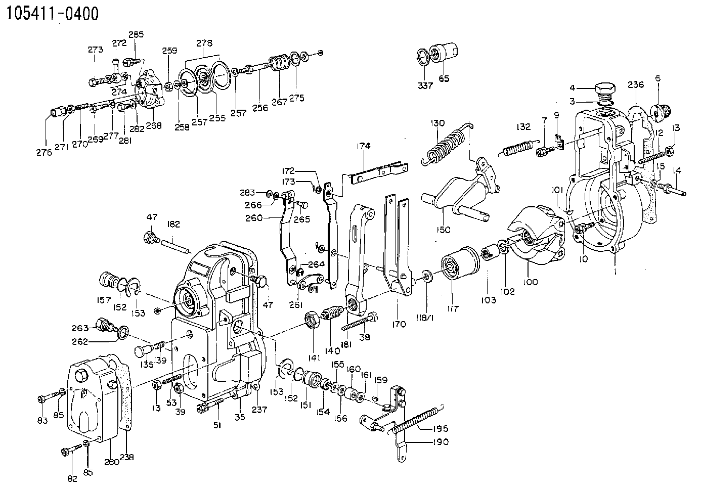
| 1. | [1] | 154000-6400 | GOVERNOR HOUSING |
| 3. | [1] | 029632-5070 | O-RING |
| 4. | [1] | 154007-2900 | CAPSULE |
| 6. | [1] | 154007-0200 | ADAPTOR |
| 7. | [1] | 020018-1840 | BLEEDER SCREW M8P1.25L18 |
| 9. | [1] | 154350-1900 | PLATE |
| 10. | [6] | 029010-6810 | BLEEDER SCREW |
| 12. | [1] | 154010-0100 | FLAT-HEAD SCREW |
| 13. | [2] | 154011-0100 | HEXAGON NUT |
| 13. | [2] | 154011-0100 | HEXAGON NUT |
| 14. | [1] | 154012-1500 | BLEEDER SCREW |
| 15. | [1] | 014110-8440 | LOCKING WASHER |
| 35. | [1] | 154022-2820 | GOVERNOR COVER |
| 38. | [1] | 154031-0100 | FLAT-HEAD SCREW |
| 39. | [1] | 013020-6020 | UNION NUT M6P1H5 |
| 47. | [2] | 154036-0300 | CAPSULE |
| 47. | [2] | 154036-0300 | CAPSULE |
| 51. | [6] | 020106-5040 | BLEEDER SCREW |
| 53. | [1] | 154010-0300 | FLAT-HEAD SCREW |
| 65. | [1] | 155404-0200 | CAP |
| 82. | [2] | 029020-6230 | BLEEDER SCREW |
| 83. | [2] | 029000-6790 | BLEEDER SCREW |
| 85. | [4] | 029320-6040 | LOCKING WASHER |
| 85. | [4] | 029320-6040 | LOCKING WASHER |
| 100. | [1] | 154100-9720 | FLYWEIGHT ASSEMBLY |
| 101. | [1] | 025803-1610 | WOODRUFF KEY |
| 102. | [1] | 029321-2020 | LOCKING WASHER |
| 103. | [1] | 029231-2030 | UNION NUT |
| 117. | [1] | 154123-0120 | SLIDING PIECE |
| 118/1. | [0] | 029311-0010 | SHIM D14&10.1T0.2 |
| 118/1. | [0] | 029311-0180 | SHIM D14&10.1T0.3 |
| 118/1. | [0] | 029311-0190 | SHIM D14&10.1T0.40 |
| 118/1. | [0] | 029311-0210 | SHIM D14&10.1T1 |
| 118/1. | [0] | 139410-0000 | SHIM D14.0&10.1T0.5 |
| 118/1. | [0] | 139410-0100 | SHIM D14.0&10.1T1.5 |
| 118/1. | [0] | 139410-3000 | SHIM D14&10.1T2.0 |
| 118/1. | [0] | 139410-3100 | SHIM D14&10.1T3.0 |
| 118/1. | [0] | 139410-3200 | SHIM D14&10.1T4.0 |
| 130. | [1] | 154150-0400 | GOVERNOR SPRING |
| 132. | [1] | 154154-0400 | COILED SPRING |
| 135. | [1] | 154160-0520 | HEADLESS SCREW |
| 139. | [1] | 154163-0100 | COILED SPRING |
| 140. | [1] | 154170-5120 | HEADLESS SCREW |
| 141. | [1] | 029201-6010 | UNION NUT |
| 150. | [1] | 154200-6920 | SWIVELLING LEVER |
| 151. | [1] | 154204-4300 | BUSHING |
| 152. | [2] | 029631-8020 | O-RING |
| 152. | [2] | 029631-8020 | O-RING |
| 153. | [2] | 016010-1640 | LOCKING WASHER |
| 153. | [2] | 016010-1640 | LOCKING WASHER |
| 154. | [1] | 139611-0000 | PACKING RING |
| 155. | [1] | 139411-0000 | SHIM |
| 156. | [0] | 029311-1070 | SHIM D16&11T0.5 |
| 157. | [1] | 154204-4400 | BUSHING |
| 159. | [1] | 025803-1310 | WOODRUFF KEY |
| 160. | [1] | 154206-2800 | BUSHING |
| 161. | [0] | 154206-0200 | PLAIN WASHER D19.5&11.2T1.0 |
| 170. | [1] | 154211-4220 | FORK LEVER |
| 172. | [3] | 029310-5170 | SHIM D8&5.3T0.5 |
| 173. | [3] | 025520-1210 | SPLIT PIN |
| 174. | [1] | 154230-0120 | STRAP |
| 181. | [1] | 154236-4100 | TENSIONING LEVER |
| 182. | [1] | 154237-0100 | BEARING PIN |
| 190. | [1] | 154303-5220 | CONTROL LEVER |
| 195. | [1] | 154314-0200 | COILED SPRING |
| 236. | [1] | 154390-0000 | GASKET |
| 237. | [1] | 154390-0300 | GASKET |
| 238. | [1] | 154351-0000 | GASKET |
| 255. | [1] | 154400-0120 | DIAPHRAGM |
| 256. | [1] | 154400-4100 | STOP PIN |
| 257. | [1] | 029340-8020 | GASKET |
| 257. | [1] | 029340-8020 | GASKET |
| 258. | [1] | 014110-6440 | LOCKING WASHER |
| 259. | [1] | 023040-6040 | UNION NUT |
| 260. | [1] | 154401-0120 | CONTROL LEVER |
| 261. | [1] | 154401-1120 | STRAP |
| 262. | [1] | 026510-1440 | GASKET D13.9&10.2T1 |
| 263. | [1] | 154401-2100 | BLEEDER SCREW |
| 264. | [1] | 016010-0540 | LOCKING WASHER |
| 265. | [1] | 154222-6200 | BEARING PIN |
| 266. | [1] | 029300-4010 | PLAIN WASHER |
| 267. | [1] | 154403-0100 | COILED SPRING |
| 268. | [1] | 154404-3900 | COVER |
| 269. | [2] | 020106-2540 | BLEEDER SCREW M6P1L25 |
| 270. | [1] | 154404-1100 | FLAT-HEAD SCREW |
| 271. | [1] | 023040-6040 | UNION NUT |
| 272. | [1] | 029711-0140 | INLET UNION |
| 273. | [1] | 029731-0180 | EYE BOLT |
| 274. | [2] | 029341-0010 | GASKET |
| 275. | [0] | 029312-0180 | SHIM D25.5&20T0.5 |
| 275B. | [0] | 029312-0210 | SHIM D25.5&20T0.2 |
| 276. | [1] | 154035-0320 | CAP NUT |
| 277. | [3] | 014110-6440 | LOCKING WASHER |
| 278. | [2] | 154413-2600 | GASKET |
| 280. | [1] | 154405-0420 | COVER |
| 281. | [1] | 029010-6010 | CAPSULE M6P1.0L7 |
| 282. | [1] | 026506-1040 | GASKET D9.9&6.2T1 |
| 283. | [1] | 016010-0440 | LOCKING WASHER |
| 285. | [1] | 029010-6310 | BLEEDER SCREW |
| 353. | [0] | 029300-8070 | PLAIN WASHER |
Include in #1:
101685-0430
as GOVERNOR
Cross reference number
Zexel num
Bosch num
Firm num
Name
105411-0400
9813203641 ISUZU
GOVERNOR
K 14JB MECHANICAL GOVERNOR GOV RSV GOV
K 14JB MECHANICAL GOVERNOR GOV RSV GOV
Information:
This Revised Service Letter replaces the 20Nov2008 Service Letter. Changes have been made to Parts Needed Description.
TERMINATION DATE
30Nov2010
PROBLEM
The existing governor linkage can separate at the riveted joint on certain C1.6 engines. If the existing governor linkage fails, it can result in loss of engine speed governing.
AFFECTED PRODUCT
Model Identification Number
C1.6 C1M00596-00703, 740-883
PARTS NEEDED
Qty
Part Number Description
1 2152619 GASKET
1 2908469 LEVER AS
1 2952235 GASKET
In order to allow equitable parts availability to all participating dealers, please limit your initial parts order to not exceed 9% of dealership population. This is an initial order recommendation only, and the ultimate responsibility for ordering the total number of parts needed to satisfy the program lies with the dealer.
ACTION REQUIRED
Gain access to engine front cover and fuel pump. Replace the existing governor linkage using the following steps.
Refer to service manual module RENR2424.
Refer to the attached Rework Procedure.
SERVICE CLAIM ALLOWANCES
Product smu/age whichever comes first Caterpillar Dealer Suggested Customer Suggested
Parts % Labor Hrs% Parts % Labor Hrs% Parts % Labor Hrs%
0-2000 hrs,
0-24 mo 100.0% 100.0% 0.0% 0.0% 0.0% 0.0%
This is a 8.0-hour job
PARTS DISPOSITION
Handle the parts in accordance with your Warranty Bulletin on warranty parts handling.
Rework Procedure
Refer to service manual module RENR2424.
1. Remove fuel injection pump. Refer to SMCS 1251-011 (Fuel Injection Pump-Remove).
2. Remove crankshaft pulley. Refer to SMCS 1205-010 (Crankshaft Pulley-Remove and Install).
3. Remove engine front cover. Refer to SMCS 1151-011 (Housing (Front) Remove).
4. Remove fuel injection pump linkage from housing. Refer to SMCS 1151-015 (Housing (Front)-Disassemble).
5. Install new 290-8469 fuel injection pump linkage. Refer to 'Installation of fuel injection pump linkage' within SMCS 1151-016 (Housing (Front)-Assemble).
6. Install engine front cover with new gasket. Refer to SMCS 1151-012 (Housing (Front)-Install).
7. Install crankshaft pulley. Refer to SMCS 1205-010 (Crankshaft Pulley - Remove and Install).
8. Install fuel injection pump. Refer to SMCS 1251-012 (Fuel Injection Pump - Install).
9. Run engine to ensure correct operation. Check for any signs of leaks.
10. Check low and high idle, and reset appropriately.
11. Refit any machine parts that were removed to gain access to engine front cover and fuel pump.