Information governor
BOSCH
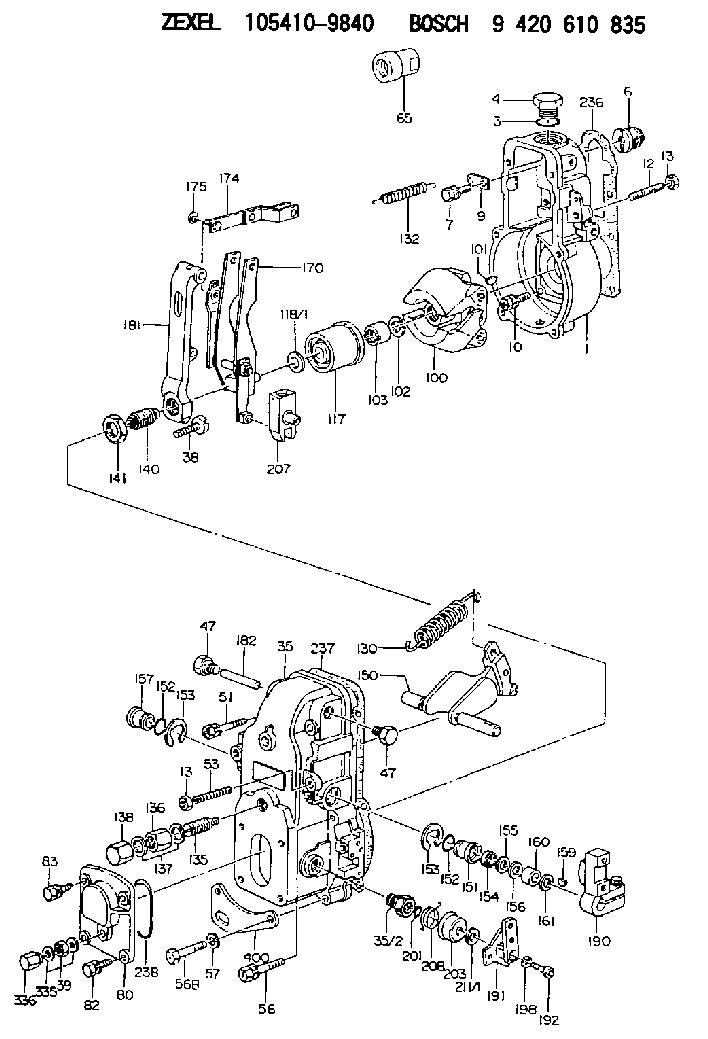
9 420 610 835
9420610835
ZEXEL
105410-9840
1054109840
NISSAN-DIESEL
1910990271
1910990271
Rating:
Scheme ###:
| 1. | [1] | 154000-6400 | GOVERNOR HOUSING |
| 3. | [1] | 029632-5070 | O-RING |
| 4. | [1] | 154007-2900 | CAPSULE |
| 6. | [1] | 154007-0200 | ADAPTOR |
| 7. | [1] | 020018-1840 | BLEEDER SCREW M8P1.25L18 |
| 9. | [1] | 154350-1900 | PLATE |
| 10. | [6] | 029010-6810 | BLEEDER SCREW |
| 12. | [1] | 154010-0100 | FLAT-HEAD SCREW |
| 13. | [2] | 154011-0100 | HEXAGON NUT |
| 13. | [2] | 154011-0100 | HEXAGON NUT |
| 35. | [1] | 154500-3020 | GOVERNOR COVER |
| 35/2. | [1] | 154321-0400 | BUSHING |
| 38. | [1] | 154031-2400 | FLAT-HEAD SCREW |
| 39. | [1] | 139206-0600 | UNION NUT |
| 47. | [2] | 154036-0300 | CAPSULE |
| 47. | [2] | 154036-0300 | CAPSULE |
| 51. | [2] | 020106-5040 | BLEEDER SCREW |
| 53. | [1] | 154010-0100 | FLAT-HEAD SCREW |
| 56. | [2] | 020106-3840 | BLEEDER SCREW |
| 56B. | [2] | 139006-8500 | BLEEDER SCREW |
| 65. | [1] | 154050-1720 | STOPPING DEVICE |
| 80. | [1] | 154064-0500 | COVER |
| 82. | [2] | 029020-6210 | BLEEDER SCREW |
| 83. | [2] | 020006-1640 | BLEEDER SCREW M6P1L16 4T |
| 100. | [1] | 154100-4520 | FLYWEIGHT ASSEMBLY |
| 101. | [1] | 025803-1610 | WOODRUFF KEY |
| 102. | [1] | 029321-2020 | LOCKING WASHER |
| 103. | [1] | 029231-2030 | UNION NUT |
| 117. | [1] | 154123-1020 | SLIDING PIECE |
| 118/1. | [0] | 029311-0010 | SHIM D14&10.1T0.2 |
| 118/1. | [0] | 029311-0180 | SHIM D14&10.1T0.3 |
| 118/1. | [0] | 029311-0190 | SHIM D14&10.1T0.40 |
| 118/1. | [0] | 029311-0210 | SHIM D14&10.1T1 |
| 118/1. | [0] | 139410-0000 | SHIM D14.0&10.1T0.5 |
| 118/1. | [0] | 139410-0100 | SHIM D14.0&10.1T1.5 |
| 118/1. | [0] | 139410-3000 | SHIM D14&10.1T2.0 |
| 118/1. | [0] | 139410-3100 | SHIM D14&10.1T3.0 |
| 118/1. | [0] | 139410-3200 | SHIM D14&10.1T4.0 |
| 130. | [1] | 154150-2700 | GOVERNOR SPRING |
| 132. | [1] | 154154-0500 | COILED SPRING |
| 135. | [1] | 154158-0820 | HEADLESS SCREW |
| 136. | [1] | 154011-1700 | UNION NUT |
| 137. | [2] | 026512-1540 | GASKET D15.4&12.2T1.50 |
| 138. | [1] | 154159-1200 | CAP NUT |
| 140. | [1] | 154177-0520 | HEADLESS SCREW |
| 141. | [1] | 029201-6010 | UNION NUT |
| 150. | [1] | 154200-7220 | SWIVELLING LEVER |
| 151. | [1] | 154204-3000 | BUSHING |
| 152. | [2] | 029631-8020 | O-RING |
| 152. | [2] | 029631-8020 | O-RING |
| 153. | [2] | 016010-1640 | LOCKING WASHER |
| 153. | [2] | 016010-1640 | LOCKING WASHER |
| 154. | [1] | 139611-0000 | PACKING RING |
| 155. | [1] | 139411-0000 | SHIM |
| 156. | [0] | 029311-1070 | SHIM D16&11T0.5 |
| 157. | [1] | 154204-3100 | BUSHING |
| 159. | [1] | 025803-1310 | WOODRUFF KEY |
| 160. | [1] | 154206-2800 | BUSHING |
| 161. | [0] | 154206-0200 | PLAIN WASHER D19.5&11.2T1.0 |
| 170. | [1] | 154211-0920 | FORK LEVER |
| 174. | [1] | 154230-3920 | STRAP |
| 175. | [1] | 016010-0540 | LOCKING WASHER |
| 181. | [1] | 154236-1500 | TENSIONING LEVER |
| 182. | [1] | 154237-0100 | BEARING PIN |
| 190. | [1] | 154340-2020 | CONTROL LEVER |
| 191. | [1] | 154364-7520 | CONTROL LEVER |
| 192. | [1] | 010206-1440 | HEX-SOCKET-HEAD CAP SCREW M6P1L14 |
| 198. | [1] | 029320-6010 | LOCKING WASHER |
| 201. | [1] | 029631-0030 | O-RING &9.8W2.3 |
| 203. | [1] | 154322-0100 | CAP |
| 207. | [1] | 154326-5120 | CONTROL LEVER |
| 208. | [1] | 154327-7300 | COILED SPRING |
| 211/1. | [0] | 029311-0520 | SHIM D20.8&10.3T0.2 |
| 211/1. | [0] | 029311-0530 | SHIM D20.8&10.3T0.25 |
| 211/1. | [0] | 029311-0540 | SHIM D20.8&10.3T0.3 |
| 211/1. | [0] | 029311-0550 | SHIM D20.8&10.3T0.35 |
| 211/1. | [0] | 029311-0560 | SHIM D20.8&10.3T0.4 |
| 211/1. | [0] | 029311-0570 | SHIM D20.8&10.3T0.5 |
| 236. | [1] | 154390-0000 | GASKET |
| 237. | [1] | 154390-0300 | GASKET |
| 238. | [1] | 029635-2020 | O-RING |
| 335. | [2] | 026506-1040 | GASKET D9.9&6.2T1 |
| 336. | [1] | 154035-1600 | CAP NUT |
| 400. | [1] | 154371-9620 | BRACKET |
Cross reference number
Zexel num
Bosch num
Firm num
Name
Information:
Image1.1.2
2. Remove existing 215-2705 cap (Image 1.2.1), and replace with new 272-7102 cap, utilizing the existing cap screws (Image 1.2.1). Insure that threads are coated with Thread Lock P/N 9S-3263 or 4C-4030 and torque cap screws to 7(+/-1) Nm.
Image1.2.1
3. Install new 263-2905 switches (Image 1.3.1) into caps insuring that threads are coated with P/N 4C-5598 High temperature Anti-Seize and torque to 16(+/-2) Nm
Image1.3.1
4. Connect new switch to the applicable wiring harness. Install ladder clips as shown (Image 1.4.1), using 0S-1588 Bolts coated with P/N 4C-5598 High Temperature Anti-Seize to replace the top two existing bolts as shown. Torque these bolts to 47 (+/-9) Nm.
Image1.4.1
Image1.4.2
5. IMPORTANT - Tie-wrap new switch wiring to existing solenoid wiring as shown (Images 1.4.1 & 1.4.2), to prevent thermal damage to wiring.
6. Install information films P/N 179-0133 on electrically actuated Air Shut Offs over the existing films on the solenoids as shown in (Image 1.6.1) or install information films for hydraulically actuated Air Shut Offs over the existing films on the valve covers as shown in (Image 1.6.2).
Films in languages other than English are available under the following part numbers:
-Arabic 297-2613
-French 297-2614
-German 297-2615
-Spanish 297-2616
-Portuguese 297-2617
-Russian 297-2618
Image1.6.1
Image1.6.2
Important Notes:
1. If a new switch is to be painted, mask the vent holes around the perimeter of the switch before painting and be sure to remove the masking after the paint dries.
2. Test completed modifications as detailed below for the specific ECM installed on the engine (ADEM 2 or ADEM 3).
OPERATIONAL TEST - ADEM 2 Engine Control Modules ONLY
Note: (For Troubleshooting purposes) The ASO switches are normally closed switches that are in the closed state when the air shutoff valves are latched in the open ("Run") position. If the air shutoff valves are in the closed ("Stop") position, the switch will be in the open state, causing an emergency stop and shutting the engine down. This also prevents the engine from starting.
DO NOT START THE ENGINE! Ensure that the engine control is in the "OFF" position.
1. Ensure that both air shutoff gates are latched in the OPEN position and ensure that both air shutoff switches are connected. Turn on the power to the engine control panel. Both air shutoff gates should remain open. If both air shutoff gates do not remain open, check the wiring for the air shutoff switches.
2. With the power for the engine control panel in the ON position, activate the "EMERGENCY STOP" switch. Both of the air shutoff gates should close. If both air shutoff gates close, proceed to step 3. If both air shutoff gates do not close, check the wiring for the air shutoff switches and check the wiring for the solenoids. Activate the "EMERGENCY STOP" switch again. When both air shutoff gates close, proceed to step 3.
3. Turn the power to the engine control panel to the OFF position. Ensure that the "EMERGENCY STOP" switch is in the RUN position. Latch only the right side air shutoff gate to the OPEN position. Turn the power for the engine control panel to