Information governor
BOSCH
F 019 Z4E 506
f019z4e506
ZEXEL
105410-9620
1054109620
MITSUBISHI
ME723856
me723856

Rating:
Scheme ###:
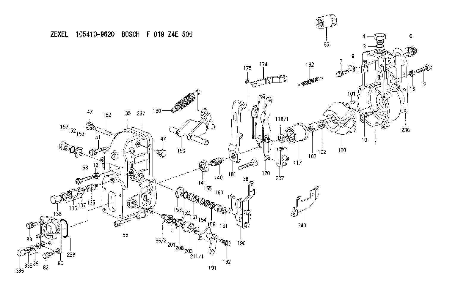
| 1. | [1] | 154000-8300 | GOVERNOR HOUSING |
| 3. | [1] | 029632-5070 | O-RING |
| 4. | [1] | 154007-2900 | CAPSULE |
| 6. | [1] | 154007-0200 | ADAPTOR |
| 7. | [1] | 020018-1840 | BLEEDER SCREW M8P1.25L18 |
| 9. | [1] | 154350-1900 | PLATE |
| 10. | [6] | 029010-6810 | BLEEDER SCREW |
| 12. | [1] | 154010-2900 | BLEEDER SCREW |
| 13. | [2] | 154011-0100 | HEXAGON NUT |
| 13. | [2] | 154011-0100 | HEXAGON NUT |
| 35. | [1] | 154500-3020 | GOVERNOR COVER |
| 35/2. | [1] | 154321-0400 | BUSHING |
| 38. | [1] | 154031-2400 | FLAT-HEAD SCREW |
| 39. | [1] | 139206-0600 | UNION NUT |
| 47. | [2] | 154036-0300 | CAPSULE |
| 47. | [2] | 154036-0300 | CAPSULE |
| 51. | [2] | 020106-5040 | BLEEDER SCREW |
| 53. | [1] | 154010-3100 | BLEEDER SCREW |
| 56. | [4] | 020106-3840 | BLEEDER SCREW |
| 65. | [1] | 155404-3800 | CAP |
| 80. | [1] | 154063-5420 | COVER |
| 82. | [2] | 029020-6210 | BLEEDER SCREW |
| 83. | [2] | 020006-1640 | BLEEDER SCREW M6P1L16 4T |
| 100. | [1] | 154101-0020 | FLYWEIGHT ASSEMBLY |
| 101. | [1] | 025803-1610 | WOODRUFF KEY |
| 102. | [1] | 029321-2020 | LOCKING WASHER |
| 103. | [1] | 029231-2030 | UNION NUT |
| 117. | [1] | 154123-0120 | SLIDING PIECE |
| 118/1. | [0] | 029311-0010 | SHIM D14&10.1T0.2 |
| 118/1. | [0] | 029311-0180 | SHIM D14&10.1T0.3 |
| 118/1. | [0] | 029311-0190 | SHIM D14&10.1T0.40 |
| 118/1. | [0] | 029311-0210 | SHIM D14&10.1T1 |
| 118/1. | [0] | 139410-0000 | SHIM D14.0&10.1T0.5 |
| 118/1. | [0] | 139410-0100 | SHIM D14.0&10.1T1.5 |
| 118/1. | [0] | 139410-3000 | SHIM D14&10.1T2.0 |
| 118/1. | [0] | 139410-3100 | SHIM D14&10.1T3.0 |
| 118/1. | [0] | 139410-3200 | SHIM D14&10.1T4.0 |
| 130. | [1] | 154150-6400 | GOVERNOR SPRING |
| 132. | [1] | 154154-0800 | COILED SPRING |
| 135. | [1] | 154158-1020 | HEADLESS SCREW |
| 136. | [1] | 154011-1700 | UNION NUT |
| 137. | [2] | 026512-1540 | GASKET D15.4&12.2T1.50 |
| 138. | [1] | 154159-1200 | CAP NUT |
| 140. | [1] | 154177-0920 | HEADLESS SCREW |
| 141. | [1] | 029201-6010 | UNION NUT |
| 150. | [1] | 154200-6920 | SWIVELLING LEVER |
| 151. | [1] | 154204-4300 | BUSHING |
| 152. | [2] | 029631-8020 | O-RING |
| 152. | [2] | 029631-8020 | O-RING |
| 153. | [2] | 016010-1640 | LOCKING WASHER |
| 153. | [2] | 016010-1640 | LOCKING WASHER |
| 154. | [1] | 139611-0000 | PACKING RING |
| 155. | [1] | 139411-0000 | SHIM |
| 156. | [0] | 029311-1070 | SHIM D16&11T0.5 |
| 157. | [1] | 154204-4400 | BUSHING |
| 159. | [1] | 025803-1310 | WOODRUFF KEY |
| 160. | [1] | 154206-2800 | BUSHING |
| 161. | [0] | 154206-0200 | PLAIN WASHER D19.5&11.2T1.0 |
| 170. | [1] | 154210-7420 | FORK LEVER |
| 174. | [1] | 154230-3920 | STRAP |
| 175. | [1] | 016010-0540 | LOCKING WASHER |
| 181. | [1] | 154236-4100 | TENSIONING LEVER |
| 182. | [1] | 154237-0100 | BEARING PIN |
| 190. | [1] | 154303-9920 | CONTROL LEVER |
| 191. | [1] | 154308-4020 | CONTROL LEVER |
| 192. | [1] | 020006-3240 | BLEEDER SCREW |
| 201. | [1] | 029631-0030 | O-RING &9.8W2.3 |
| 203. | [1] | 154322-0100 | CAP |
| 207. | [1] | 154326-5120 | CONTROL LEVER |
| 208. | [1] | 154327-7800 | COILED SPRING |
| 211/1. | [0] | 029311-0520 | SHIM D20.8&10.3T0.2 |
| 211/1. | [0] | 029311-0530 | SHIM D20.8&10.3T0.25 |
| 211/1. | [0] | 029311-0540 | SHIM D20.8&10.3T0.3 |
| 211/1. | [0] | 029311-0550 | SHIM D20.8&10.3T0.35 |
| 211/1. | [0] | 029311-0560 | SHIM D20.8&10.3T0.4 |
| 211/1. | [0] | 029311-0570 | SHIM D20.8&10.3T0.5 |
| 236. | [1] | 154390-0000 | GASKET |
| 237. | [1] | 154390-0300 | GASKET |
| 238. | [1] | 029635-2020 | O-RING |
| 335. | [2] | 026506-1040 | GASKET D9.9&6.2T1 |
| 336. | [1] | 154035-1600 | CAP NUT |
| 340. | [1] | 154213-5800 | BRACKET |
Include in #1:
101602-1130
as GOVERNOR
Cross reference number
Zexel num
Bosch num
Firm num
Name
Information:
Installation Procedure
Illustration 1 g06123834
Remove support (1) from the engine compartment.
Illustration 2 g06123840
Locate insulation (2) on the engine hood.
Illustration 3 g06123843
Raise the insulation approximately 30 mm (1.2 inch) to avoid interference with the new tank.
Illustration 4 g06123848
Loosen the worm-drive clamps and remove two hoses (3) from the DEF system. Save the cushion clamps and hardware for reuse.
Illustration 5 g06123850
(4) 428-8808 Hose Clamp
(5) 467-9633 Hose
(6) Cushion clamp (reuse)
Install hose (5) and two clamps (4). Slowly tighten the clamps to 6.6 0.2 N m (58 1.8 lb in). Install cushion clamp (6) (previously removed) onto the hose.
Illustration 6 g06123852
(4) 428-8808 Hose Clamp
(6) Cushion clamp (reuse)
(7) 469-6277 Hose
(8) 424-1209 Tank
Connect one end of hose (7) to the tube on the engine using clamp (4). Slowly tighten the clamp to 6.6 0.2 N m (58 1.8 lb in). Install cushion clamp (6) (previously removed) onto the hose.
Connect the other end of the hose to the upper port on tank (8). Install clamp (4). Slowly tighten the clamp to 6.6 0.2 N m (58 1.8 lb in).
Illustration 7 g06123862
(4) 428-8808 Hose Clamp
(9) 469-9636 Hose
(10) 6V-3250 O-Ring Seal
(11) 7X-1448 Elbow
Install elbow (11) and O-Ring seal (10) on the tank. Install hose (9) using two hose clamps (4). Slowly tighten the clamps to 6.6 0.2 N m (58 1.8 lb in) while ensuring hose (9) stays at a 30 degree angle from the top tank hose.
Illustration 8 g06123868
(12) 454-4235 Plate
(13) 326-4516 Cable Tie
Secure the two hoses together using plate (12) and two cable ties (13).
Illustration 9 g06123873
(8) 424-1209 Tank
(14) 471-9825 Support As
(15) 8T-4189 Bolt
(16) 8T-4224 Hard Washer
Install support (14) in place of the original support.
Secure tank (8) to the support using two bolts (15) and two washers (16).
Install new machine, engine, and after treatment software.The new software is available in the form of a flash file through the Caterpillar Service Information System (SIS). A newer part number may be available. SIS web only displays the latest available flash file.
Illustration 10 g06123878
Update the DES threshold to 525 degrees C using Cat® Electronic Technician (Cat ET). A factory password is required to change the value. A factory password can be obtained after inputting your Corporate Web Security (CWS) identification.