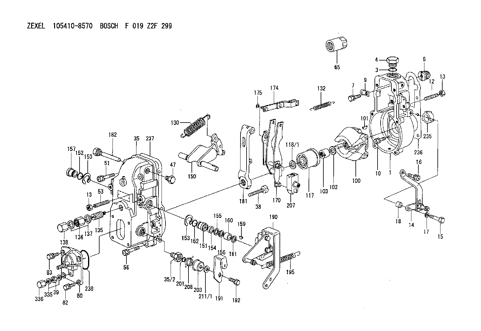
Information governor
BOSCH
F 019 Z2F 299
f019z2f299
ZEXEL
105410-8570
1054108570

Rating:
Scheme ###:
| 1. | [1] | 154004-1400 | GOVERNOR HOUSING |
| 3. | [1] | 029632-5070 | O-RING |
| 4. | [1] | 154007-2900 | CAPSULE |
| 6. | [1] | 154007-0200 | ADAPTOR |
| 7. | [1] | 020018-1840 | BLEEDER SCREW M8P1.25L18 |
| 9. | [1] | 154350-1900 | PLATE |
| 10. | [6] | 029010-6810 | BLEEDER SCREW |
| 12. | [1] | 154010-0100 | FLAT-HEAD SCREW |
| 13. | [2] | 154011-0100 | HEXAGON NUT |
| 13. | [2] | 154011-0100 | HEXAGON NUT |
| 14. | [1] | 154355-8020 | BRACKET |
| 15. | [1] | 020118-3240 | BLEEDER SCREW |
| 16. | [1] | 029010-5180 | BLEEDER SCREW |
| 17. | [1] | 014110-5440 | LOCKING WASHER |
| 18. | [1] | 154355-8700 | SPACER BUSHING |
| 35. | [1] | 154500-3020 | GOVERNOR COVER |
| 35/2. | [1] | 154321-0400 | BUSHING |
| 38. | [1] | 154031-2400 | FLAT-HEAD SCREW |
| 39. | [1] | 139206-0600 | UNION NUT |
| 47. | [1] | 154036-0300 | CAPSULE |
| 51. | [2] | 020106-5040 | BLEEDER SCREW |
| 53. | [1] | 154010-0200 | FLAT-HEAD SCREW |
| 56. | [4] | 020106-3840 | BLEEDER SCREW |
| 65. | [1] | 155404-5700 | CAP |
| 80. | [1] | 154063-6820 | COVER |
| 82. | [2] | 029020-6210 | BLEEDER SCREW |
| 83. | [2] | 020006-1640 | BLEEDER SCREW M6P1L16 4T |
| 100. | [1] | 154101-0020 | FLYWEIGHT ASSEMBLY |
| 101. | [1] | 025803-1610 | WOODRUFF KEY |
| 102. | [1] | 029321-2020 | LOCKING WASHER |
| 103. | [1] | 029231-2030 | UNION NUT |
| 117. | [1] | 154123-0120 | SLIDING PIECE |
| 118/1. | [0] | 029311-0010 | SHIM D14&10.1T0.2 |
| 118/1. | [0] | 029311-0180 | SHIM D14&10.1T0.3 |
| 118/1. | [0] | 029311-0190 | SHIM D14&10.1T0.40 |
| 118/1. | [0] | 029311-0210 | SHIM D14&10.1T1 |
| 118/1. | [0] | 139410-0000 | SHIM D14.0&10.1T0.5 |
| 118/1. | [0] | 139410-0100 | SHIM D14.0&10.1T1.5 |
| 118/1. | [0] | 139410-3000 | SHIM D14&10.1T2.0 |
| 118/1. | [0] | 139410-3100 | SHIM D14&10.1T3.0 |
| 118/1. | [0] | 139410-3200 | SHIM D14&10.1T4.0 |
| 130. | [1] | 154150-6400 | GOVERNOR SPRING |
| 132. | [1] | 154154-0800 | COILED SPRING |
| 135. | [1] | 154158-1020 | HEADLESS SCREW |
| 136. | [1] | 154011-1700 | UNION NUT |
| 137. | [2] | 026512-1540 | GASKET D15.4&12.2T1.50 |
| 138. | [1] | 154159-1200 | CAP NUT |
| 150. | [1] | 154200-6920 | SWIVELLING LEVER |
| 151. | [1] | 154204-4300 | BUSHING |
| 152. | [2] | 029631-8020 | O-RING |
| 152. | [2] | 029631-8020 | O-RING |
| 153. | [2] | 016010-1640 | LOCKING WASHER |
| 153. | [2] | 016010-1640 | LOCKING WASHER |
| 154. | [1] | 139611-0000 | PACKING RING |
| 155. | [1] | 139411-0000 | SHIM |
| 156. | [0] | 029311-1070 | SHIM D16&11T0.5 |
| 157. | [1] | 154204-4400 | BUSHING |
| 159. | [1] | 025803-1310 | WOODRUFF KEY |
| 160. | [1] | 154206-2800 | BUSHING |
| 161. | [0] | 154206-0200 | PLAIN WASHER D19.5&11.2T1.0 |
| 170. | [1] | 154210-7420 | FORK LEVER |
| 174. | [1] | 154230-3920 | STRAP |
| 175. | [1] | 016010-0540 | LOCKING WASHER |
| 181. | [1] | 154236-4100 | TENSIONING LEVER |
| 182. | [1] | 154237-1100 | BEARING PIN |
| 190. | [1] | 154347-0420 | CONTROL LEVER |
| 191. | [1] | 154304-9100 | CONTROL LEVER |
| 192. | [1] | 020006-1640 | BLEEDER SCREW M6P1L16 4T |
| 195. | [1] | 154314-9000 | COILED SPRING |
| 201. | [1] | 029631-0030 | O-RING &9.8W2.3 |
| 203. | [1] | 154322-0100 | CAP |
| 207. | [1] | 154326-5120 | CONTROL LEVER |
| 208. | [1] | 154327-7300 | COILED SPRING |
| 211/1. | [0] | 029311-0520 | SHIM D20.8&10.3T0.2 |
| 211/1. | [0] | 029311-0530 | SHIM D20.8&10.3T0.25 |
| 211/1. | [0] | 029311-0540 | SHIM D20.8&10.3T0.3 |
| 211/1. | [0] | 029311-0550 | SHIM D20.8&10.3T0.35 |
| 211/1. | [0] | 029311-0560 | SHIM D20.8&10.3T0.4 |
| 211/1. | [0] | 029311-0570 | SHIM D20.8&10.3T0.5 |
| 235. | [1] | 155412-5200 | IMPELLER WHEEL |
| 236. | [1] | 154390-0000 | GASKET |
| 237. | [1] | 154390-0300 | GASKET |
| 238. | [1] | 029635-2020 | O-RING |
| 335. | [2] | 026506-1040 | GASKET D9.9&6.2T1 |
| 336. | [1] | 154035-1600 | CAP NUT |
Cross reference number
Zexel num
Bosch num
Firm num
Name
Information:
Remove the single tie bolt (6) that is located in the top left corner of the pump by using Tooling (B). Refer to Illustration 7. Only remove the single tie bolt (6). Removing more bolts will result in damage to the pump.
Illustration 2 g01132938
(1) HEUI pump (2) Fuel transfer pump (4) Drive gear (5) 227-5904 O-Ring Seal (6) Tie Bolt (7) Bolts for the fuel transfer pump (8) Tie Bolts (9) Location for service bolt (12) 185-3241 O-Ring Seal
Replace tie bolt (6) with the temporary service bolt (9) that is provided in the service kit.Note: The service bolt that is provided in the kit has an undersized bolt head. The service bolt prevents the body of the HEUI pump from separating during service. Do not remove the service bolt until the fuel transfer pump has been completely reinstalled.
Tighten the service bolt (9) to 10 N m (7.4 lb ft) by using Tooling (C) .Note: Do not place an excessive torque on the service bolt. The aluminum housing of the pump could be damaged.
After installing the service bolt (9) in the top left location, remove the three bolts (7) that fasten the fuel transfer pump to the HEUI pump by using Tooling (A) .
Proceed by removing the remaining three tie bolts (8) by using Tooling (B) .
Separate the fuel transfer pump from the HEUI pump. Refer to Illustration 3.
Illustration 3 g01132944
(1) HEUI pump (2) Fuel transfer pump (9) Service bolt (10) Seals (11) SealInstalling the Fuel Transfer Pump onto the HEUI Pump
Install the two new 239-2402 Seals (10) on the back face of the HEUI pump (1). Refer to Illustration 4.
Illustration 4 g01077898
(1) HEUI pump (10) 239-2402 Seals
Install a new 179-8128 Seal (11) on the fuel transfer pump (2). Refer to Illustration 5. Use 1U-6396 O-Ring Assembly Compound in order to hold the seal in place during assembly. Ensure that the seal is completely seated.
Illustration 5 g01132957
(2) Fuel transfer pump (11) 179-8128 Seal
Do not remove the service bolt. Position the fuel transfer pump on the HEUI pump. Be sure to properly align the drive tang on the fuel transfer pump with the drive slot on the HEUI pump.Note: Align the drive tang of the fuel transfer pump so that the flat end is vertical. Refer to Illustration 5. Align the drive slot in the HEUI pump to a similar vertical orientation by using a flat head screwdriver. Refer to Illustration 6.
Illustration 6 g01132969
Note: Once the fuel transfer pump has been placed onto the HEUI pump, ensure that the face of the fuel transfer pump is flush with the face of the HEUI pump. If the pump faces are not flush, verify the alignment of the drive tang.
Install the three mounting bolts (7) for the fuel transfer pump (2). Tighten