Information governor
BOSCH
F 019 Z2F 441
f019z2f441
ZEXEL
105410-7850
1054107850
Rating:
Scheme ###:
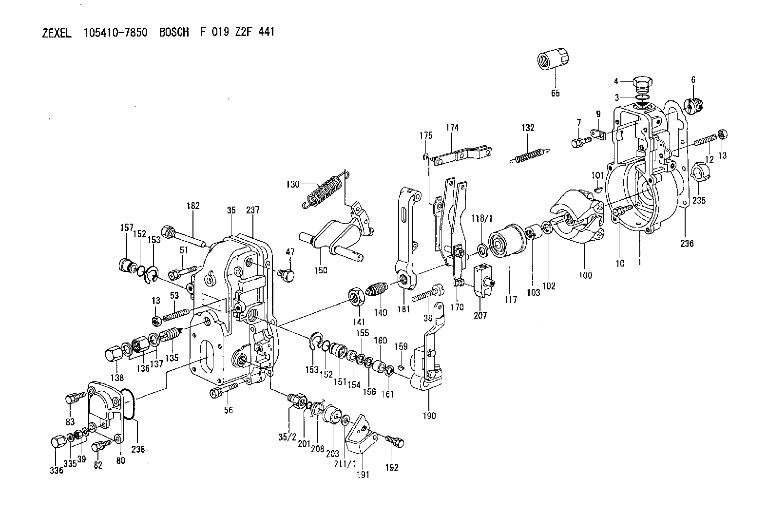
| 1. | [1] | 154000-6400 | GOVERNOR HOUSING |
| 3. | [1] | 029632-5070 | O-RING |
| 4. | [1] | 154007-2900 | CAPSULE |
| 6. | [1] | 154007-0200 | ADAPTOR |
| 7. | [1] | 020018-1840 | BLEEDER SCREW M8P1.25L18 |
| 9. | [1] | 154350-1900 | PLATE |
| 10. | [6] | 029010-6810 | BLEEDER SCREW |
| 12. | [1] | 154010-0100 | FLAT-HEAD SCREW |
| 13. | [2] | 154011-0100 | HEXAGON NUT |
| 13. | [2] | 154011-0100 | HEXAGON NUT |
| 35. | [1] | 154500-3020 | GOVERNOR COVER |
| 35/2. | [1] | 154321-0400 | BUSHING |
| 38. | [1] | 154031-2400 | FLAT-HEAD SCREW |
| 39. | [1] | 139206-0600 | UNION NUT |
| 47. | [1] | 154036-0300 | CAPSULE |
| 51. | [2] | 020106-5040 | BLEEDER SCREW |
| 53. | [1] | 154010-0100 | FLAT-HEAD SCREW |
| 56. | [4] | 020106-3840 | BLEEDER SCREW |
| 65. | [1] | 155404-5700 | CAP |
| 80. | [1] | 154063-1400 | COVER |
| 82. | [2] | 029020-6210 | BLEEDER SCREW |
| 83. | [2] | 020006-1640 | BLEEDER SCREW M6P1L16 4T |
| 100. | [1] | 154100-9720 | FLYWEIGHT ASSEMBLY |
| 101. | [1] | 025803-1610 | WOODRUFF KEY |
| 102. | [1] | 029321-2020 | LOCKING WASHER |
| 103. | [1] | 029231-2030 | UNION NUT |
| 117. | [1] | 154123-0120 | SLIDING PIECE |
| 118/1. | [0] | 029311-0010 | SHIM D14&10.1T0.2 |
| 118/1. | [0] | 029311-0180 | SHIM D14&10.1T0.3 |
| 118/1. | [0] | 029311-0190 | SHIM D14&10.1T0.40 |
| 118/1. | [0] | 029311-0210 | SHIM D14&10.1T1 |
| 118/1. | [0] | 139410-0000 | SHIM D14.0&10.1T0.5 |
| 118/1. | [0] | 139410-0100 | SHIM D14.0&10.1T1.5 |
| 118/1. | [0] | 139410-3000 | SHIM D14&10.1T2.0 |
| 118/1. | [0] | 139410-3100 | SHIM D14&10.1T3.0 |
| 118/1. | [0] | 139410-3200 | SHIM D14&10.1T4.0 |
| 130. | [1] | 154150-2900 | GOVERNOR SPRING |
| 132. | [1] | 154154-0701 | COILED SPRING |
| 135. | [1] | 154158-1720 | HEADLESS SCREW |
| 136. | [1] | 154011-1700 | UNION NUT |
| 137. | [2] | 026512-1540 | GASKET D15.4&12.2T1.50 |
| 138. | [1] | 154159-1200 | CAP NUT |
| 140. | [1] | 154177-2220 | HEADLESS SCREW |
| 141. | [1] | 029201-6010 | UNION NUT |
| 150. | [1] | 154200-6920 | SWIVELLING LEVER |
| 151. | [1] | 154204-4300 | BUSHING |
| 152. | [2] | 029631-8020 | O-RING |
| 152. | [2] | 029631-8020 | O-RING |
| 153. | [2] | 016010-1640 | LOCKING WASHER |
| 153. | [2] | 016010-1640 | LOCKING WASHER |
| 154. | [1] | 139611-0000 | PACKING RING |
| 155. | [1] | 139411-0000 | SHIM |
| 156. | [0] | 029311-1070 | SHIM D16&11T0.5 |
| 157. | [1] | 154204-4400 | BUSHING |
| 159. | [1] | 025803-1310 | WOODRUFF KEY |
| 160. | [1] | 154206-2800 | BUSHING |
| 161. | [0] | 154206-0200 | PLAIN WASHER D19.5&11.2T1.0 |
| 170. | [1] | 154210-0820 | FORK LEVER |
| 174. | [1] | 154230-3920 | STRAP |
| 175. | [1] | 016010-0540 | LOCKING WASHER |
| 181. | [1] | 154236-4100 | TENSIONING LEVER |
| 182. | [1] | 154237-1100 | BEARING PIN |
| 190. | [1] | 154341-8320 | CONTROL LEVER |
| 191. | [1] | 154366-1600 | CONTROL LEVER |
| 192. | [1] | 020006-1640 | BLEEDER SCREW M6P1L16 4T |
| 201. | [1] | 029631-0030 | O-RING &9.8W2.3 |
| 203. | [1] | 154322-0100 | CAP |
| 207. | [1] | 154326-5120 | CONTROL LEVER |
| 208. | [1] | 154327-7500 | COILED SPRING |
| 211/1. | [0] | 029311-0520 | SHIM D20.8&10.3T0.2 |
| 211/1. | [0] | 029311-0530 | SHIM D20.8&10.3T0.25 |
| 211/1. | [0] | 029311-0540 | SHIM D20.8&10.3T0.3 |
| 211/1. | [0] | 029311-0550 | SHIM D20.8&10.3T0.35 |
| 211/1. | [0] | 029311-0560 | SHIM D20.8&10.3T0.4 |
| 211/1. | [0] | 029311-0570 | SHIM D20.8&10.3T0.5 |
| 235. | [1] | 155412-5200 | IMPELLER WHEEL |
| 236. | [1] | 154390-0000 | GASKET |
| 237. | [1] | 154390-0300 | GASKET |
| 238. | [1] | 029635-2020 | O-RING |
| 335. | [2] | 026506-1040 | GASKET D9.9&6.2T1 |
| 336. | [1] | 154035-1600 | CAP NUT |
Include in #1:
101601-3230
as GOVERNOR
Cross reference number
Zexel num
Bosch num
Firm num
Name
105410-7850
F 019 Z2F 441
GOVERNOR
* K
* K
Information:
Illustration 16 g00628694
(9) Fuel injector clamp. (10) Bolt. (11) O-ring seal.
Place the clamp (9) in the proper position. Temporarily place the jumper tube in position in order to ensure alignment of the bolt holes. Adjust the orientation of the injector until the alignment is satisfactory. Torque the bolt (10) to the following torque. Remove the jumper tube.Torque for bolt ... 47 9 N m (35 7 lb ft)
Illustration 17 g00628691
(12) O-ring seals in the injector jumper tube. (13) O-ring seals in the base of the rocker arm.
Replace the used O-ring seal (11), and the O-ring seals (12) and (13) in the jumper tube and in the rocker arm.
Illustration 18 g00628693
(14) Jumper tube. (15) Bolts. (16) Adapter. (17) Socket head screws.
Place the jumper tube (14) and the adapter (16) into position.
If the adapter was previously installed on the injector, loosen the socket head screws. Failure to loosen the socket head screws before continuing with Step 8 can result in injector failure.
Install the socket head screws (17) and the four bolts (15) finger tight.Note: The mating surfaces should be brought into complete contact and into alignment before the final torque procedure is started.
Failure to follow any of the procedures in this instruction may result in injector damage or malfunction, and possible major engine damage.
Torque Procedure
Illustration 19 g00338156
(1) Socket head screws.
Illustration 20 g00338157
(2) Two horizontal bolts. (3) Two vertical bolts.
Tighten the socket head screws (1), the two horizontal bolts (2), and the two vertical bolts (3) finger tight.
Tighten the socket head screws (1) to an initial torque of 1 .2 N m (9 2 lb in).
Tighten the horizontal bolts (2) to an initial torque of 5 3 N m (44 27 lb in).
Tighten the vertical bolts (3) to an initial torque of 5 3 N m (44 27 lb in).
Tighten the socket head screws (1) to a final torque of 12 3 N m (9 2 lb ft).
Tighten the horizontal bolts (2) to a final torque of 47 9 N m (35 7 lb ft).
Tighten the vertical bolts (3) to a final torque of 47 9 N m (35 7 lb ft).
Repeat Step 1 through Step 7 for the remainder of the injectors.
Check the fuel system for leaks by cranking the engine with the disabled injection. Then check the hydraulic pressure. Compare the pressure to the desired pressure.Cranking Without Injecting
Cranking the engine with the disabled injection may be performed by one of the following methods:
Disconnect the injector harness of the cylinders which have been reinstalled. Allow the engine to idle. Visually inspect the injector's components for high pressure oil leaks.
Activate the system "Crank Without Inject" if the option is available. On Track-Type Tractors, a "Crank Without Inject" plug can be assembled in the engine harness. On Off-Highway Trucks, the "Ground Level Shutdown" can be activated if the option is available.
When you are using the CAT ET or the ECAP, the injection may be disabled by interactive diagnostics. The engine can be left
Have questions with 105410-7850?
Group cross 105410-7850 ZEXEL
105410-7850
F 019 Z2F 441
GOVERNOR