Information governor
BOSCH
F 019 Z1E 780
f019z1e780
ZEXEL
105410-7290
1054107290
Rating:
Scheme ###:
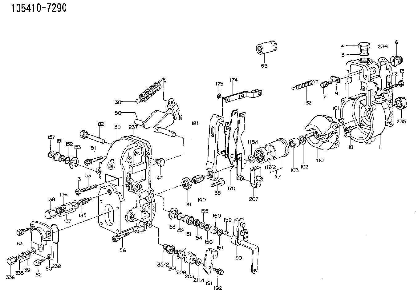
| 1. | [1] | 154000-6400 | GOVERNOR HOUSING |
| 3. | [1] | 029632-5070 | O-RING |
| 4. | [1] | 154007-2900 | CAPSULE |
| 6. | [1] | 154007-0200 | ADAPTOR |
| 7. | [1] | 020018-1840 | BLEEDER SCREW M8P1.25L18 |
| 9. | [1] | 154350-1900 | PLATE |
| 10. | [6] | 029010-6810 | BLEEDER SCREW |
| 12. | [1] | 154010-1100 | FLAT-HEAD SCREW |
| 13. | [2] | 154011-0100 | HEXAGON NUT |
| 13. | [2] | 154011-0100 | HEXAGON NUT |
| 35. | [1] | 154500-3020 | GOVERNOR COVER |
| 35/2. | [1] | 154321-0400 | BUSHING |
| 38. | [1] | 154031-2400 | FLAT-HEAD SCREW |
| 39. | [1] | 139206-0600 | UNION NUT |
| 47. | [1] | 154036-0300 | CAPSULE |
| 51. | [2] | 020106-5040 | BLEEDER SCREW |
| 53. | [1] | 154010-0200 | FLAT-HEAD SCREW |
| 56. | [4] | 020106-3840 | BLEEDER SCREW |
| 65. | [1] | 155404-5700 | CAP |
| 80. | [1] | 154063-1400 | COVER |
| 82. | [2] | 029020-6210 | BLEEDER SCREW |
| 83. | [2] | 020006-1640 | BLEEDER SCREW M6P1L16 4T |
| 100. | [1] | 154100-9720 | FLYWEIGHT ASSEMBLY |
| 101. | [1] | 025803-1610 | WOODRUFF KEY |
| 102. | [1] | 029321-2020 | LOCKING WASHER |
| 103. | [1] | 029231-2030 | UNION NUT |
| 117. | [1] | 154123-0120 | SLIDING PIECE |
| 118/1. | [0] | 029311-0010 | SHIM D14&10.1T0.2 |
| 118/1. | [0] | 029311-0180 | SHIM D14&10.1T0.3 |
| 118/1. | [0] | 029311-0190 | SHIM D14&10.1T0.40 |
| 118/1. | [0] | 029311-0210 | SHIM D14&10.1T1 |
| 118/1. | [0] | 139410-0000 | SHIM D14.0&10.1T0.5 |
| 118/1. | [0] | 139410-0100 | SHIM D14.0&10.1T1.5 |
| 118/1. | [0] | 139410-3000 | SHIM D14&10.1T2.0 |
| 118/1. | [0] | 139410-3100 | SHIM D14&10.1T3.0 |
| 118/1. | [0] | 139410-3200 | SHIM D14&10.1T4.0 |
| 130. | [1] | 154150-2700 | GOVERNOR SPRING |
| 132. | [1] | 154154-0701 | COILED SPRING |
| 135. | [1] | 154158-1720 | HEADLESS SCREW |
| 136. | [1] | 154011-1700 | UNION NUT |
| 137. | [2] | 026512-1540 | GASKET D15.4&12.2T1.50 |
| 138. | [1] | 154159-1200 | CAP NUT |
| 140. | [1] | 154177-1920 | HEADLESS SCREW |
| 141. | [1] | 029201-6010 | UNION NUT |
| 150. | [1] | 154200-7220 | SWIVELLING LEVER |
| 151. | [1] | 154204-4300 | BUSHING |
| 151. | [1] | 154204-4300 | BUSHING |
| 152. | [2] | 029631-8020 | O-RING |
| 152. | [2] | 029631-8020 | O-RING |
| 153. | [2] | 016010-1640 | LOCKING WASHER |
| 153. | [2] | 016010-1640 | LOCKING WASHER |
| 154. | [1] | 139611-0000 | PACKING RING |
| 155. | [1] | 139411-0000 | SHIM |
| 156. | [0] | 029311-1070 | SHIM D16&11T0.5 |
| 157. | [1] | 154204-4400 | BUSHING |
| 159. | [1] | 025803-1310 | WOODRUFF KEY |
| 160. | [1] | 154206-2800 | BUSHING |
| 161. | [0] | 154206-0200 | PLAIN WASHER D19.5&11.2T1.0 |
| 170. | [1] | 154210-0820 | FORK LEVER |
| 174. | [1] | 154230-3920 | STRAP |
| 175. | [1] | 016010-0540 | LOCKING WASHER |
| 181. | [1] | 154236-1500 | TENSIONING LEVER |
| 182. | [1] | 154237-1100 | BEARING PIN |
| 190. | [1] | 154341-6220 | CONTROL LEVER |
| 191. | [1] | 154304-9100 | CONTROL LEVER |
| 192. | [1] | 020006-1640 | BLEEDER SCREW M6P1L16 4T |
| 201. | [1] | 029631-0030 | O-RING &9.8W2.3 |
| 203. | [1] | 154322-0100 | CAP |
| 207. | [1] | 154326-5120 | CONTROL LEVER |
| 208. | [1] | 154327-7300 | COILED SPRING |
| 211/1. | [0] | 029311-0520 | SHIM D20.8&10.3T0.2 |
| 211/1. | [0] | 029311-0530 | SHIM D20.8&10.3T0.25 |
| 211/1. | [0] | 029311-0540 | SHIM D20.8&10.3T0.3 |
| 211/1. | [0] | 029311-0550 | SHIM D20.8&10.3T0.35 |
| 211/1. | [0] | 029311-0560 | SHIM D20.8&10.3T0.4 |
| 211/1. | [0] | 029311-0570 | SHIM D20.8&10.3T0.5 |
| 235. | [1] | 155412-5200 | IMPELLER WHEEL |
| 236. | [1] | 154390-0000 | GASKET |
| 237. | [1] | 154390-0300 | GASKET |
| 238. | [1] | 029635-2020 | O-RING |
| 335. | [2] | 026506-1040 | GASKET D9.9&6.2T1 |
| 336. | [1] | 154035-1800 | CAP NUT |
Cross reference number
Zexel num
Bosch num
Firm num
Name
105410-7290
F 019 Z1E 780
GOVERNOR
* K
* K
Information:
Product smu/age whichever comes first Caterpillar Dealer Suggested Customer Suggested
Parts % Labor Hrs% Parts % Labor Hrs% Parts % Labor Hrs%
*******Group 2*******
0-6000 hrs,
0-48 mo 100.0% 100.0% 0.0% 0.0% 0.0% 0.0%
This is a 4.0-hour job for Group 2
PARTS DISPOSITION
Handle the parts in accordance with your Warranty Bulletin on warranty parts handling.
Rework Procedure
1. Park the machine on level ground, lower all implements to the ground, shut off machine, and relieve all hydraulic system pressure.
2. Read and understand this Rework Procedure before starting work.
3. See Image 1.2.1 for the general location of the DEF Module Group and reference views that will be used in future steps.
Image1.2.1
(A) Fuel tank; (B) Diesel Exhaust Fluid (DEF) Module Group
DEF tank cover not shown for clarity
4. Inspect control harness assembly (2) at location (AA) and hose assembly (3) at location (BB) for rubbing and or fouling on the DEF Tank Cover (See Image 1.4.1). If either item is damaged, replace both assembly (2) and (3).
396-3862 Control Harness Assembly (2) is compatible with serial numbers equipped WITHOUT a DEF Quality Sensor (FMC1-00772). 524-5527 Control Harness Assembly (2) is compatible with serial numbers equipped WITH a DEF Quality Sensor (FMC00773-Up).
Hardware (C) holding the DEF Module Group to the fuel tank and clamp (E) holding DEF Fill Hose (D) to the tank will need to be loosened to reposition the DEF Module Group to access control harness assembly (2) and hose assembly (3).
Image1.4.1
5. After control harness assembly (2) and hose assembly (3) have been inspected and found without damage OR replaced, secure both parts using Steps 6 through 9.
6. Secure control harness assembly (2) and hose assembly (3) to left side of DEF Module (F) using tie straps (4). (See Image 1.6.1)
The Fuel tank is not shown for clarity.
Image1.6.1
At location (CC), use tie straps (4) to secure harness bundles (G) to prevent harness from contacting the fuel tank. (See Image 1.7.1)
Image1.7.1
At location (DD), use tie straps (4) to secure control harness assembly (2) and hose assembly (3), and terminating resistor (H) at lower location. (See Image 1.8.1)
Image1.8.1
7. Reposition the DEF Module Group, install 560-4252 Bracket Assembly (1), and reinstall the remaining hardware (C), clamp (E) removed in Step 4. Check to make sure control harness assembly (2) and hose assembly (3) will not contact the DEF Tank Cover. (See Image 1.9.1)
Image1.9.1
8. Secure control harness assembly (2) and hose assembly (3) to top of DEF Module Group using tie straps (4) as shown in Image 1.10.1. Check to make sure control harness assembly (2) and hose assembly (3) will not contact the DEF Tank Cover.
Note: Existing P-clip (J) will need to be flipped from the original position.
Image1.10.1
9. Secure control harness assembly (2) and hose assembly (3) to the rear and right side of Diesel Exhaust Fluid Module using tie straps (4) as shown in Image 1.11.1. Check to make sure control harness assembly (2) and hose assembly (3) will not contact the DEF Tank Cover.
Image1.11.1
Have questions with 105410-7290?
Group cross 105410-7290 ZEXEL
Isuzu
M.Bishi-Hi.-Nag
105410-7290
F 019 Z1E 780
GOVERNOR