Information governor
BOSCH
F 019 Z1E 093
f019z1e093
ZEXEL
105410-7170
1054107170
ISUZU
8941331890
8941331890
Rating:
Scheme ###:
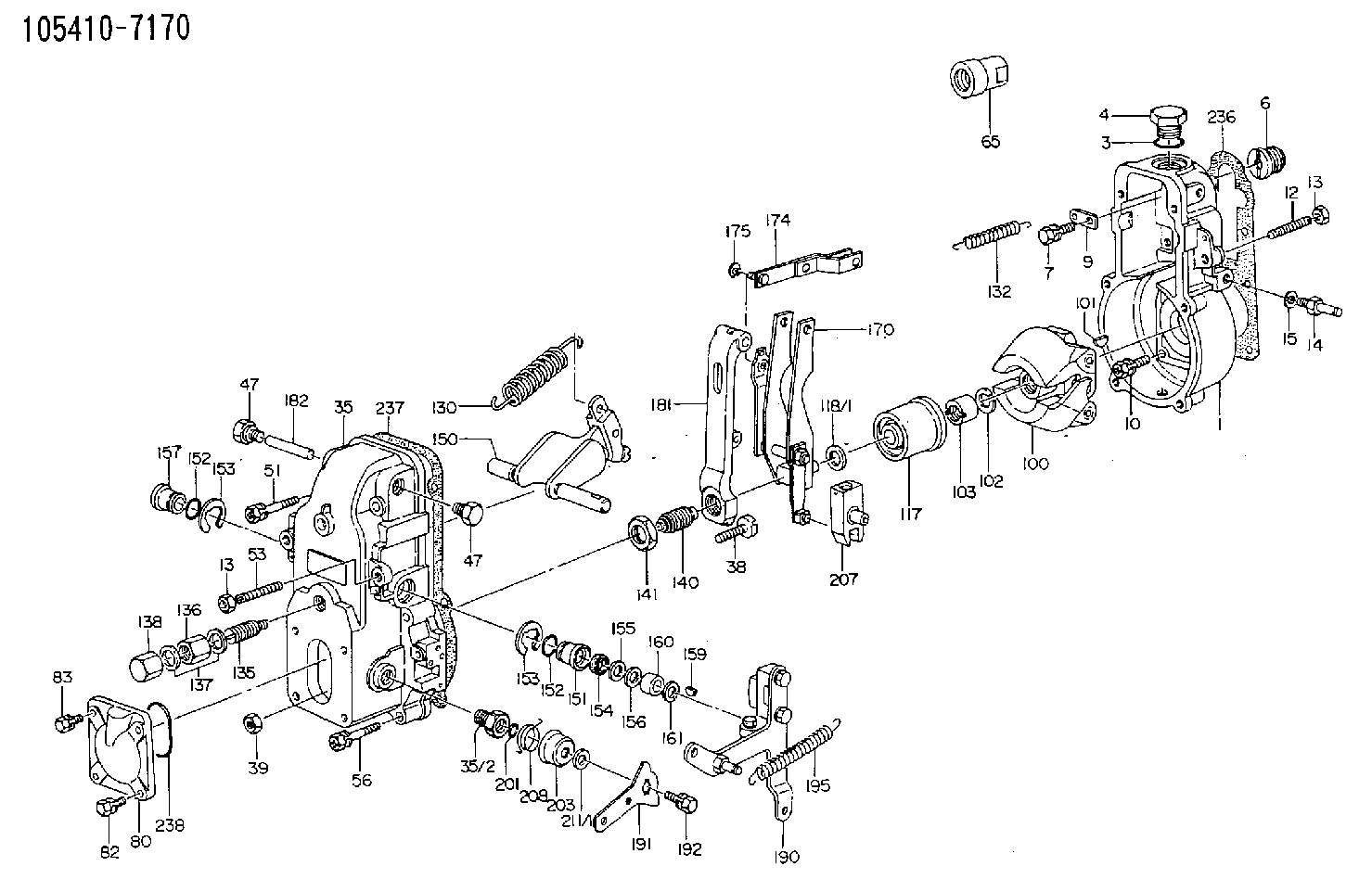
| 1. | [1] | 154000-6400 | GOVERNOR HOUSING |
| 3. | [1] | 029632-5070 | O-RING |
| 4. | [1] | 154007-2900 | CAPSULE |
| 6. | [1] | 154007-0200 | ADAPTOR |
| 7. | [1] | 020018-1840 | BLEEDER SCREW M8P1.25L18 |
| 9. | [1] | 154350-1900 | PLATE |
| 10. | [6] | 029010-6810 | BLEEDER SCREW |
| 12. | [1] | 154010-0100 | FLAT-HEAD SCREW |
| 13. | [2] | 154011-0100 | HEXAGON NUT |
| 13. | [2] | 154011-0100 | HEXAGON NUT |
| 14. | [1] | 154012-1500 | BLEEDER SCREW |
| 15. | [1] | 014110-8440 | LOCKING WASHER |
| 35. | [1] | 154500-3020 | GOVERNOR COVER |
| 35/2. | [1] | 154321-0400 | BUSHING |
| 38. | [1] | 154031-0100 | FLAT-HEAD SCREW |
| 39. | [1] | 013020-6020 | UNION NUT M6P1H5 |
| 47. | [2] | 154036-0300 | CAPSULE |
| 47. | [2] | 154036-0300 | CAPSULE |
| 51. | [2] | 020106-5040 | BLEEDER SCREW |
| 53. | [1] | 154010-0100 | FLAT-HEAD SCREW |
| 56. | [4] | 020106-3840 | BLEEDER SCREW |
| 65. | [1] | 155404-0200 | CAP |
| 80. | [1] | 154063-1800 | COVER |
| 82. | [2] | 029020-6210 | BLEEDER SCREW |
| 83. | [2] | 020006-1640 | BLEEDER SCREW M6P1L16 4T |
| 100. | [1] | 154100-9720 | FLYWEIGHT ASSEMBLY |
| 101. | [1] | 025803-1610 | WOODRUFF KEY |
| 102. | [1] | 029321-2020 | LOCKING WASHER |
| 103. | [1] | 029231-2030 | UNION NUT |
| 117. | [1] | 154123-0120 | SLIDING PIECE |
| 118/1. | [0] | 029311-0010 | SHIM D14&10.1T0.2 |
| 118/1. | [0] | 029311-0180 | SHIM D14&10.1T0.3 |
| 118/1. | [0] | 029311-0190 | SHIM D14&10.1T0.40 |
| 118/1. | [0] | 029311-0210 | SHIM D14&10.1T1 |
| 118/1. | [0] | 139410-0000 | SHIM D14.0&10.1T0.5 |
| 118/1. | [0] | 139410-0100 | SHIM D14.0&10.1T1.5 |
| 118/1. | [0] | 139410-3000 | SHIM D14&10.1T2.0 |
| 118/1. | [0] | 139410-3100 | SHIM D14&10.1T3.0 |
| 118/1. | [0] | 139410-3200 | SHIM D14&10.1T4.0 |
| 130. | [1] | 154150-2700 | GOVERNOR SPRING |
| 132. | [1] | 154154-1200 | COILED SPRING |
| 135. | [1] | 154158-1820 | HEADLESS SCREW |
| 136. | [1] | 154011-1700 | UNION NUT |
| 137. | [2] | 026512-1540 | GASKET D15.4&12.2T1.50 |
| 138. | [1] | 154159-1200 | CAP NUT |
| 140. | [1] | 154185-1320 | HEADLESS SCREW |
| 141. | [1] | 029201-6010 | UNION NUT |
| 150. | [1] | 154200-7220 | SWIVELLING LEVER |
| 151. | [1] | 154204-4300 | BUSHING |
| 152. | [2] | 029631-8020 | O-RING |
| 152. | [2] | 029631-8020 | O-RING |
| 153. | [2] | 016010-1640 | LOCKING WASHER |
| 153. | [2] | 016010-1640 | LOCKING WASHER |
| 154. | [1] | 139611-0000 | PACKING RING |
| 155. | [1] | 139411-0000 | SHIM |
| 156. | [0] | 029311-1070 | SHIM D16&11T0.5 |
| 157. | [1] | 154204-4400 | BUSHING |
| 159. | [1] | 025803-1310 | WOODRUFF KEY |
| 160. | [1] | 154206-2800 | BUSHING |
| 161. | [0] | 154206-0200 | PLAIN WASHER D19.5&11.2T1.0 |
| 170. | [1] | 154210-0820 | FORK LEVER |
| 174. | [1] | 154230-3920 | STRAP |
| 175. | [1] | 016010-0540 | LOCKING WASHER |
| 181. | [1] | 154236-1500 | TENSIONING LEVER |
| 182. | [1] | 154237-0100 | BEARING PIN |
| 190. | [1] | 154303-5220 | CONTROL LEVER |
| 191. | [1] | 154307-4100 | CONTROL LEVER |
| 192. | [1] | 020006-1640 | BLEEDER SCREW M6P1L16 4T |
| 195. | [1] | 154314-0200 | COILED SPRING |
| 201. | [1] | 029631-0030 | O-RING &9.8W2.3 |
| 203. | [1] | 154322-0100 | CAP |
| 207. | [1] | 154326-5120 | CONTROL LEVER |
| 208. | [1] | 154327-7300 | COILED SPRING |
| 211/1. | [0] | 029311-0520 | SHIM D20.8&10.3T0.2 |
| 211/1. | [0] | 029311-0530 | SHIM D20.8&10.3T0.25 |
| 211/1. | [0] | 029311-0540 | SHIM D20.8&10.3T0.3 |
| 211/1. | [0] | 029311-0550 | SHIM D20.8&10.3T0.35 |
| 211/1. | [0] | 029311-0560 | SHIM D20.8&10.3T0.4 |
| 211/1. | [0] | 029311-0570 | SHIM D20.8&10.3T0.5 |
| 236. | [1] | 154390-0000 | GASKET |
| 237. | [1] | 154390-0300 | GASKET |
| 238. | [1] | 029635-2020 | O-RING |
Include in #1:
101431-0930
as GOVERNOR
Cross reference number
Zexel num
Bosch num
Firm num
Name
Information:
PARTS DISPOSITION
Handle the parts in accordance with your Warranty Bulletin on warranty parts handling.
Rework Procedure
Diesel Exhaust Fluid Pressure Line Removal Process:
1. Follow the Disassembly and Assembly, UENR4468, for Diesel Exhaust Fluid Lines ? Remove and Install, steps 1 to 9 to remove the DEF pressure line.
2. Remove p-clips (3) and (4) on the plate attached to the hydraulic tank and on the sound wall support leg. Keep the bolt and washer from p-clip (4) as it will be used to install the new pressure line (Image1.1.1).
Image1.1.1
3. Remove p-clip (8) from the inside of the frame and p-clips (10,12) inside of the DEF enclosure from the diesel exhaust fluid pressure line (11) (Image1.2.1).
4. Cut cable ties (9,13) near the PETU from the diesel exhaust fluid pressure line (11) (Image1.2.1).
5. Pull the diesel exhaust fluid pressure line (11) out of the machine (Image1.2.1).
Image1.2.1
DEF Injector Replacement ? Remove and Install:
1. Remove DEF injector and replace. Follow Disassembly and Assembly, UENR6559, for DEF Injector and Mounting - Remove and Install.
New Diesel Exhaust Fluid Pressure Line Preparation:
1. Lay the 3.65 m pressure line out straight on a flat surface
2. Measure 308 mm from the mating point of the line and the connector and mark the location
3. Measure 631 mm from the mating point of the line and the connector and mark the location
4. Measure 996 mm from the mating point of the line and the connector and mark the location
5. Measure 1386 mm from the mating point of the line and the connector and mark the location
6. Place p-clip (6D-4246) on the line with its edge on the 1st mark
7. Place p-clip (336-8614) on the line with its edge on the 2nd mark
8. Place p-clip (336-8614) on the line with its edge on the 3rd mark
9. Place p-clip (336-8614) on the line with its edge on the 4th mark
Note: Keep lines capped when measuring and placing the p-clips
Image1.4.1
Machine Preparation:
1. Remove bracket (1) from machine. Keep the bolt and washer as it will be used when installing the new pressure line (Image1.5.1).
2. Drill an 11 mm diameter hole in the hood support. Refer to Image1.5.2 for location and Image1.5.3 for dimensions.
3. Remove the bolt and washer on the hydraulic tank support plate and keep as it will be used when installing the new diesel exhaust fluid pressure line (Image1.5.4).
Image1.5.1
Image1.5.2
Image1.5.3
Image1.5.4
Installation Process:
1. Remove plugs from the new diesel exhaust fluid pressure line
2. Attach p-clip 6D-4246 (1) and hose to the newly drilled 11 mm hole in the hood support using hardware nut 344-5675 (qty. 1), washer 8T-4121 (qty. 2), and bolt 8T-4195 (qty. 1). Once attached, the p-clip should be oriented at 15 degrees from vertical pointing downwards. Torque hardware to 55 Nm (Image1.6.1).
Image1.6.1
3. Attach p-clip 336-8614 (2) to the hydraulic tank and secure using the removed hardware (bolt: 8T-4136 and washer: 7X-7729) from step 3 of the machine preparation. Once attached, the p-clip should be oriented at 30 degrees from vertical pointing upwards to maintain the upwards slope of the line towards the hydraulic tank. Torque hardware to 55 Nm once p-clip is oriented correctly (Image1.7.1.).
Image1.7.1
4. Connect the diesel exhaust fluid line to the DEF injector
5. Attach