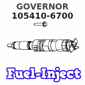
Information governor
BOSCH
F 019 Z1E 599
f019z1e599
ZEXEL
105410-6700
1054106700
Rating:
Scheme ###:
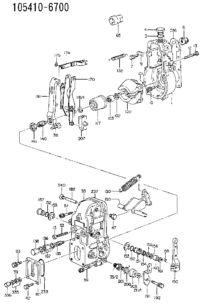
| 1. | [1] | 154000-6400 | GOVERNOR HOUSING |
| 3. | [1] | 029632-5070 | O-RING |
| 4. | [1] | 154007-2900 | CAPSULE |
| 6. | [1] | 154007-0200 | ADAPTOR |
| 7. | [1] | 020018-1840 | BLEEDER SCREW M8P1.25L18 |
| 9. | [1] | 154350-1900 | PLATE |
| 10. | [6] | 029010-6810 | BLEEDER SCREW |
| 12. | [1] | 154010-0100 | FLAT-HEAD SCREW |
| 13. | [2] | 154011-0100 | HEXAGON NUT |
| 13. | [2] | 154011-0100 | HEXAGON NUT |
| 35. | [1] | 154500-6720 | GOVERNOR COVER |
| 35/2. | [1] | 154321-0400 | BUSHING |
| 38. | [1] | 154031-2200 | FLAT-HEAD SCREW |
| 39. | [1] | 139206-0600 | UNION NUT |
| 47. | [1] | 154036-0300 | CAPSULE |
| 51. | [2] | 020106-5040 | BLEEDER SCREW |
| 53. | [1] | 154010-0100 | FLAT-HEAD SCREW |
| 56. | [4] | 020106-3840 | BLEEDER SCREW |
| 65. | [1] | 154050-6120 | STOPPING DEVICE |
| 80. | [1] | 154060-8800 | COVER |
| 82. | [2] | 020506-1440 | BLEEDER SCREW |
| 83. | [2] | 020006-1440 | BLEEDER SCREW M6P1L14 |
| 85. | [2] | 014110-6440 | LOCKING WASHER |
| 100. | [1] | 154100-4820 | FLYWEIGHT ASSEMBLY |
| 101. | [1] | 025803-1610 | WOODRUFF KEY |
| 102. | [1] | 029321-2020 | LOCKING WASHER |
| 103. | [1] | 029231-2030 | UNION NUT |
| 117. | [1] | 154123-1420 | SLIDING PIECE |
| 118/1. | [0] | 029311-0010 | SHIM D14&10.1T0.2 |
| 118/1. | [0] | 029311-0180 | SHIM D14&10.1T0.3 |
| 118/1. | [0] | 029311-0190 | SHIM D14&10.1T0.40 |
| 118/1. | [0] | 029311-0210 | SHIM D14&10.1T1 |
| 118/1. | [0] | 139410-0000 | SHIM D14.0&10.1T0.5 |
| 118/1. | [0] | 139410-0100 | SHIM D14.0&10.1T1.5 |
| 118/1. | [0] | 139410-3000 | SHIM D14&10.1T2.0 |
| 118/1. | [0] | 139410-3100 | SHIM D14&10.1T3.0 |
| 118/1. | [0] | 139410-3200 | SHIM D14&10.1T4.0 |
| 130. | [1] | 154150-6400 | GOVERNOR SPRING |
| 132. | [1] | 154154-0800 | COILED SPRING |
| 135. | [1] | 154158-3220 | HEADLESS SCREW |
| 136. | [1] | 154011-1700 | UNION NUT |
| 137. | [2] | 026512-1540 | GASKET D15.4&12.2T1.50 |
| 138. | [1] | 154159-1200 | CAP NUT |
| 140. | [1] | 154178-9220 | HEADLESS SCREW |
| 141. | [1] | 029201-6010 | UNION NUT |
| 150. | [1] | 154200-7220 | SWIVELLING LEVER |
| 151. | [1] | 154204-3000 | BUSHING |
| 152. | [2] | 029631-8020 | O-RING |
| 152. | [2] | 029631-8020 | O-RING |
| 153. | [2] | 016010-1640 | LOCKING WASHER |
| 153. | [2] | 016010-1640 | LOCKING WASHER |
| 154. | [1] | 139611-0000 | PACKING RING |
| 155. | [1] | 139411-0000 | SHIM |
| 156. | [0] | 029311-1070 | SHIM D16&11T0.5 |
| 157. | [1] | 154204-3100 | BUSHING |
| 159. | [1] | 025803-1310 | WOODRUFF KEY |
| 160. | [1] | 154206-2800 | BUSHING |
| 161. | [0] | 154206-0200 | PLAIN WASHER D19.5&11.2T1.0 |
| 170. | [1] | 154211-0920 | FORK LEVER |
| 174. | [1] | 154230-3920 | STRAP |
| 175. | [1] | 016010-0540 | LOCKING WASHER |
| 181. | [1] | 154236-1500 | TENSIONING LEVER |
| 182. | [1] | 154237-0100 | BEARING PIN |
| 190. | [1] | 154309-6120 | CONTROL LEVER |
| 191. | [1] | 154301-5700 | CONTROL LEVER |
| 192. | [1] | 020006-1640 | BLEEDER SCREW M6P1L16 4T |
| 201. | [1] | 029631-0030 | O-RING &9.8W2.3 |
| 203. | [1] | 154322-0100 | CAP |
| 207. | [1] | 154326-5120 | CONTROL LEVER |
| 208. | [1] | 154327-7300 | COILED SPRING |
| 211/1. | [0] | 029311-0520 | SHIM D20.8&10.3T0.2 |
| 211/1. | [0] | 029311-0530 | SHIM D20.8&10.3T0.25 |
| 211/1. | [0] | 029311-0540 | SHIM D20.8&10.3T0.3 |
| 211/1. | [0] | 029311-0550 | SHIM D20.8&10.3T0.35 |
| 211/1. | [0] | 029311-0560 | SHIM D20.8&10.3T0.4 |
| 211/1. | [0] | 029311-0570 | SHIM D20.8&10.3T0.5 |
| 236. | [1] | 154390-0000 | GASKET |
| 237. | [1] | 154390-0300 | GASKET |
| 238. | [1] | 029635-5010 | O-RING |
| 335. | [2] | 026506-1040 | GASKET D9.9&6.2T1 |
| 336. | [1] | 154035-1600 | CAP NUT |
| 340. | [1] | 154036-0700 | CAPSULE |
Include in #1:
101641-9110
as GOVERNOR
Cross reference number
Zexel num
Bosch num
Firm num
Name
Information:
If there has been a previous repair, part age/hours will apply. Retain a copy of the previous repair invoice in the dealer's records for audit purposes, and specify repair date and machine hours in the "Additional Comments" section of the warranty claim.
PARTS DISPOSITION
****Parts Stock****
Handle the parts in accordance with your Warranty Bulletin on warranty parts handling.
****Affected Product****
Handle the parts in accordance with your Warranty Bulletin on warranty parts handling.
Rework Procedure
Note: Ensure that all safety information, warnings, and instructions are read and understood before any operation or any maintenance procedures are performed. Refer to the Operation and Maintenance Manual "Safety Section".
C175 Injector Sleeve Re-Seal Process:
This Rework Procedure outlines how to correctly remove, inspect, and install a C175 injector sleeve into a cylinder head, with a new process designed to stop coolant leaks caused by injector sleeve seal failure.
Parts and Materials Needed:
8T-2223 Quill Tube Bolts/Cylinder - Qty 4
8T-0106 injector Hold Down Bolt/Cylinder - Qty 1
298-5347 Injector Sleeve/Cylinder - Qty 1
247-1074 Injector Sleeve O-Rings/Cylinder - Qty 2
8C-3132 Injector Tip O-Ring/Cylinder - Qty 1
339-9352 Injector System Cap Kit/Engine - Qty 1
- Battery powered screwdriver/impact
- Soft bristled brush (nylon or other non-metallic material), Cat part number 6V-7096 is an example. Refer to Image1.2.1.
- Injector sleeve torque tool (333-0759, or new tool provided by Lafayette)
- Vacuum attachment, for removing debris from inside cylinder
- Deep well socket, inverted
- Wrap a lint free shop towel around the socket, secure to the socket with an O-ring
- Brake clean or similar solvent
- Torque wrench capable of reaching 200 N.m
- Anti-seize (C5-A Loctite 51007)
- Clean engine oil
Image1.2.1
Removal of Valve Covers:
1. Remove four quill tube bolts and slide quill out of head. Refer to Image1.3.1.
2. Place quill tube into sealed plastic bag.
3. Place plugs into the quill tube hole and over fuel limiter in the fuel rail.
4. Remove the injectors.
5. Place injectors in plastic bag.
Image1.3.1
Removal of the Injector Sleeves:
1. Remove the injector sleeves. Refer to Image 1.4.1.
2. Vacuum out any loose debris.
3. Clean remaining Loctite debris from the injector sleeve seat using brake-clean or a similar solvent, a nylon bristled brush (Cat part number 6V-7096), and an inverted socket with a lint free rag or towel wrapped around it).
4. Use an O-ring to keep the rag around the socket.
5. Clean the threads in the head with the soft bristled brush. Refer to Image1.4.2.
6. Clean the seat surface with the inverted socket and a new rag until the rag no longer picks up debris or dirt from the seat. Refer to Image1.4.3 and 1.4.4.
Image1.4.1
Image1.4.2
Image1.4.3
Image1.4.4
Inspection of the Injector Sleeve Seat:
1. The seat and threads must be free of any debris.
2. The seat must not have any visible guttering around the surface.
3. There should be a continuous shiny band