Information governor
BOSCH
F 019 Z1F 013
f019z1f013
ZEXEL
105410-6380
1054106380
Rating:
Scheme ###:
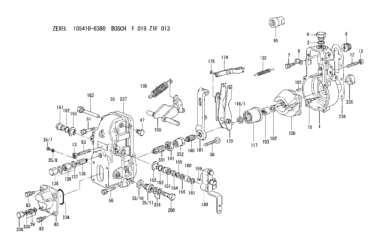
| 1. | [1] | 154000-6400 | GOVERNOR HOUSING |
| 3. | [1] | 029632-5070 | O-RING |
| 4. | [1] | 154007-2900 | CAPSULE |
| 6. | [1] | 154007-0200 | ADAPTOR |
| 7. | [1] | 020018-1840 | BLEEDER SCREW M8P1.25L18 |
| 9. | [1] | 154350-1900 | PLATE |
| 10. | [6] | 029010-6810 | BLEEDER SCREW |
| 12. | [1] | 154010-0100 | FLAT-HEAD SCREW |
| 13. | [2] | 154011-0100 | HEXAGON NUT |
| 13. | [2] | 154011-0100 | HEXAGON NUT |
| 35. | [1] | 154500-7520 | GOVERNOR COVER |
| 35/7. | [1] | 154222-2700 | FLAT-HEAD SCREW |
| 35/8. | [1] | 014110-3440 | LOCKING WASHER |
| 35/10. | [1] | 026516-2040 | GASKET D19.9&16.2T1 |
| 35/11. | [1] | 154316-6600 | ADAPTOR |
| 38. | [1] | 154031-3000 | FLAT-HEAD SCREW |
| 39. | [1] | 139206-0600 | UNION NUT |
| 47. | [1] | 154036-0300 | CAPSULE |
| 51. | [2] | 020106-5040 | BLEEDER SCREW |
| 53. | [1] | 154010-0300 | FLAT-HEAD SCREW |
| 56. | [4] | 020106-3840 | BLEEDER SCREW |
| 65. | [1] | 154050-1720 | STOPPING DEVICE |
| 80. | [1] | 154063-5100 | COVER |
| 82. | [2] | 029020-6210 | BLEEDER SCREW |
| 83. | [2] | 020006-1640 | BLEEDER SCREW M6P1L16 4T |
| 100. | [1] | 154100-9720 | FLYWEIGHT ASSEMBLY |
| 101. | [1] | 025803-1610 | WOODRUFF KEY |
| 102. | [1] | 029321-2020 | LOCKING WASHER |
| 103. | [1] | 029231-2030 | UNION NUT |
| 117. | [1] | 154123-0120 | SLIDING PIECE |
| 118/1. | [0] | 029311-0010 | SHIM D14&10.1T0.2 |
| 118/1. | [0] | 029311-0180 | SHIM D14&10.1T0.3 |
| 118/1. | [0] | 029311-0190 | SHIM D14&10.1T0.40 |
| 118/1. | [0] | 029311-0210 | SHIM D14&10.1T1 |
| 118/1. | [0] | 139410-0000 | SHIM D14.0&10.1T0.5 |
| 118/1. | [0] | 139410-0100 | SHIM D14.0&10.1T1.5 |
| 118/1. | [0] | 139410-3000 | SHIM D14&10.1T2.0 |
| 118/1. | [0] | 139410-3100 | SHIM D14&10.1T3.0 |
| 118/1. | [0] | 139410-3200 | SHIM D14&10.1T4.0 |
| 130. | [1] | 154150-2700 | GOVERNOR SPRING |
| 132. | [1] | 154154-0701 | COILED SPRING |
| 135. | [1] | 154158-0820 | HEADLESS SCREW |
| 136. | [1] | 154011-1700 | UNION NUT |
| 137. | [2] | 026512-1540 | GASKET D15.4&12.2T1.50 |
| 138. | [1] | 154159-1200 | CAP NUT |
| 140. | [1] | 154185-2220 | HEADLESS SCREW |
| 141. | [1] | 029201-6080 | UNION NUT |
| 150. | [1] | 154200-7220 | SWIVELLING LEVER |
| 151. | [1] | 154204-4300 | BUSHING |
| 152. | [2] | 029631-8020 | O-RING |
| 152. | [2] | 029631-8020 | O-RING |
| 153. | [2] | 016010-1640 | LOCKING WASHER |
| 153. | [2] | 016010-1640 | LOCKING WASHER |
| 154. | [1] | 139611-0000 | PACKING RING |
| 155. | [1] | 139411-0000 | SHIM |
| 156. | [0] | 029311-1070 | SHIM D16&11T0.5 |
| 157. | [1] | 154204-4400 | BUSHING |
| 159. | [1] | 025803-1310 | WOODRUFF KEY |
| 160. | [1] | 154206-2800 | BUSHING |
| 161. | [0] | 154206-0200 | PLAIN WASHER D19.5&11.2T1.0 |
| 170. | [1] | 154211-3820 | FORK LEVER |
| 174. | [1] | 154230-0120 | STRAP |
| 175. | [1] | 016010-0540 | LOCKING WASHER |
| 181. | [1] | 154236-1500 | TENSIONING LEVER |
| 182. | [1] | 154237-1100 | BEARING PIN |
| 190. | [1] | 154341-7820 | CONTROL LEVER |
| 235. | [1] | 155412-5200 | IMPELLER WHEEL |
| 236. | [1] | 154390-0000 | GASKET |
| 237. | [1] | 154390-0300 | GASKET |
| 238. | [1] | 029635-2020 | O-RING |
| 250. | [1] | 029731-2040 | EYE BOLT |
| 251. | [2] | 029341-2140 | GASKET |
| 331. | [1] | 154179-0620 | HEADLESS SCREW |
| 332. | [1] | 029201-6010 | UNION NUT |
| 335. | [2] | 026506-1040 | GASKET D9.9&6.2T1 |
| 336. | [1] | 154035-1600 | CAP NUT |
Include in #1:
101602-3670
as GOVERNOR
Cross reference number
Zexel num
Bosch num
Firm num
Name
Information:
Start By:a. remove oil pump 1. Check each main bearing cap (2) for its location on the engine. Each cap has an arrow (1) which shows the direction of the front of the block and a number (3) which gives the location of that cap.2. Remove No. 2 through No. 6 main bearing caps from the engine. Remove the lower bearings from the caps.3. Remove the thrust plate from each side of the No. 4 upper main bearing. 4. Turn the crankshaft until Tool (A) can be installed in oil hole (4). Turn the crankshaft in the direction which will push the upper main bearing out, tab end first.
If the crankshaft is turned in the wrong direction, the tab of the bearing will be pushed between the crankshaft and the cylinder block. This will cause damage to the crankshaft and block.
Install the main bearings dry when clearance checks are made. Put clean engine oil on the main bearings for final assembly. 5. Install lower bearings in the bearing caps.6. Install upper bearings in the cylinder block with Tool (A). Be sure tab (5) on the back of the bearings fits in the groove of the caps and cylinder block. When the bearing clearance is checked and the engine is in a vertical position such as in the vehicle, the crankshaft will have to be lifted up and held against the upper halves of the main bearings to get a correct measurement with plastigage (B). The Plastigage will not hold the weight of the crankshaft and give a correct indication. If the engine is in a horizontal position, such as on an engine stand, it is not necessary to hold the crankshaft up. Do not turn crankshaft when the Plastigage is in position to check clearance.
Do not use an impact wrench to tighten the bolts the additional 120 degrees.
7. Check the bearing clearance with Plastigage (B) as follows:a. Put clean oil on the threads of the cap bolts. Install the caps and cap bolts, finger tight.b. Tighten the bolts on the tab end of the caps first to a torque of 260 14 N m (190 10 lb ft)c. Tighten the bolts on the other end of the caps to a torque of 260 14 N m (190 10 lb ft).d. Put a mark across the bolt head and cap. Tighten the bolts opposite the tab end 120 degrees more. Tighten the bolts on the tab end of the cap 120 degrees more. Make sure the main bearing caps are installed with their identification number (7) in alignment with the identification number on the left side of the cylinder block and arrow (6) toward the front of the block.8. Remove the main bearing caps and Tool (B).9. Measure the thickness of the Plastigage to find the bearing clearance. The clearance for new bearings must be 0.091 to 0.186 mm (.0036 to .0073 in). The maximum clearance for used bearings is 0.025 mm (0.010 in).10.