Information governor
BOSCH
F 019 Z1E 775
f019z1e775
ZEXEL
105410-6290
1054106290
Rating:
Scheme ###:
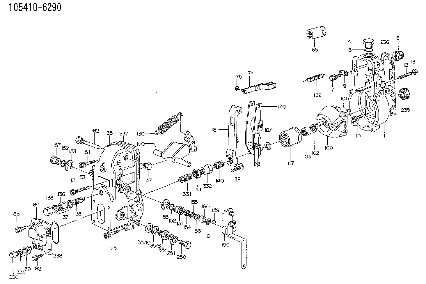
| 1. | [1] | 154000-6400 | GOVERNOR HOUSING |
| 3. | [1] | 029632-5070 | O-RING |
| 4. | [1] | 154007-2900 | CAPSULE |
| 6. | [1] | 154007-0200 | ADAPTOR |
| 7. | [1] | 020018-1840 | BLEEDER SCREW M8P1.25L18 |
| 9. | [1] | 154350-1900 | PLATE |
| 10. | [6] | 029010-6810 | BLEEDER SCREW |
| 12. | [1] | 154010-0100 | FLAT-HEAD SCREW |
| 13. | [2] | 154011-0100 | HEXAGON NUT |
| 13. | [2] | 154011-0100 | HEXAGON NUT |
| 35. | [1] | 154500-7520 | GOVERNOR COVER |
| 35/7. | [1] | 154222-2700 | FLAT-HEAD SCREW |
| 35/8. | [1] | 014110-3440 | LOCKING WASHER |
| 35/10. | [1] | 026516-2040 | GASKET D19.9&16.2T1 |
| 35/11. | [1] | 154316-6600 | ADAPTOR |
| 38. | [1] | 154031-3000 | FLAT-HEAD SCREW |
| 39. | [1] | 139206-0600 | UNION NUT |
| 47. | [1] | 154036-0300 | CAPSULE |
| 51. | [2] | 020106-5040 | BLEEDER SCREW |
| 53. | [1] | 154010-0300 | FLAT-HEAD SCREW |
| 56. | [4] | 020106-3840 | BLEEDER SCREW |
| 65. | [1] | 154050-1720 | STOPPING DEVICE |
| 80. | [1] | 154063-5100 | COVER |
| 82. | [2] | 029020-6210 | BLEEDER SCREW |
| 83. | [2] | 020006-1640 | BLEEDER SCREW M6P1L16 4T |
| 100. | [1] | 154100-9720 | FLYWEIGHT ASSEMBLY |
| 101. | [1] | 025803-1610 | WOODRUFF KEY |
| 102. | [1] | 029321-2020 | LOCKING WASHER |
| 103. | [1] | 029231-2030 | UNION NUT |
| 117. | [1] | 154123-0120 | SLIDING PIECE |
| 118/1. | [0] | 029311-0010 | SHIM D14&10.1T0.2 |
| 118/1. | [0] | 029311-0180 | SHIM D14&10.1T0.3 |
| 118/1. | [0] | 029311-0190 | SHIM D14&10.1T0.40 |
| 118/1. | [0] | 029311-0210 | SHIM D14&10.1T1 |
| 118/1. | [0] | 139410-0000 | SHIM D14.0&10.1T0.5 |
| 118/1. | [0] | 139410-0100 | SHIM D14.0&10.1T1.5 |
| 118/1. | [0] | 139410-3000 | SHIM D14&10.1T2.0 |
| 118/1. | [0] | 139410-3100 | SHIM D14&10.1T3.0 |
| 118/1. | [0] | 139410-3200 | SHIM D14&10.1T4.0 |
| 130. | [1] | 154150-2700 | GOVERNOR SPRING |
| 132. | [1] | 154154-0701 | COILED SPRING |
| 135. | [1] | 154158-0820 | HEADLESS SCREW |
| 136. | [1] | 154011-1700 | UNION NUT |
| 137. | [2] | 026512-1540 | GASKET D15.4&12.2T1.50 |
| 138. | [1] | 154159-1200 | CAP NUT |
| 140. | [1] | 154178-7020 | HEADLESS SCREW |
| 141. | [1] | 029201-6080 | UNION NUT |
| 150. | [1] | 154200-7220 | SWIVELLING LEVER |
| 151. | [1] | 154204-4300 | BUSHING |
| 152. | [2] | 029631-8020 | O-RING |
| 152. | [2] | 029631-8020 | O-RING |
| 153. | [2] | 016010-1640 | LOCKING WASHER |
| 153. | [2] | 016010-1640 | LOCKING WASHER |
| 154. | [1] | 139611-0000 | PACKING RING |
| 155. | [1] | 139411-0000 | SHIM |
| 156. | [0] | 029311-1070 | SHIM D16&11T0.5 |
| 157. | [1] | 154204-4400 | BUSHING |
| 159. | [1] | 025803-1310 | WOODRUFF KEY |
| 160. | [1] | 154206-2800 | BUSHING |
| 161. | [0] | 154206-0200 | PLAIN WASHER D19.5&11.2T1.0 |
| 170. | [1] | 154211-3820 | FORK LEVER |
| 174. | [1] | 154230-0120 | STRAP |
| 175. | [1] | 016010-0540 | LOCKING WASHER |
| 181. | [1] | 154236-1500 | TENSIONING LEVER |
| 182. | [1] | 154237-1100 | BEARING PIN |
| 190. | [1] | 154341-7820 | CONTROL LEVER |
| 236. | [1] | 154390-0000 | GASKET |
| 237. | [1] | 154390-0300 | GASKET |
| 238. | [1] | 029635-2020 | O-RING |
| 250. | [1] | 029731-2040 | EYE BOLT |
| 251. | [2] | 029341-2140 | GASKET |
| 331. | [1] | 154179-3920 | HEADLESS SCREW |
| 332. | [1] | 029201-6010 | UNION NUT |
| 335. | [2] | 026506-1040 | GASKET D9.9&6.2T1 |
| 336. | [1] | 154035-1600 | CAP NUT |
Include in #1:
101602-3480
as GOVERNOR
Cross reference number
Zexel num
Bosch num
Firm num
Name
105410-6290
F 019 Z1E 775
GOVERNOR
* K
* K
Information:
Start By:a. remove rocker shaft assembliesb. remove turbochargers1. Remove the valve cover bases from the cylinder head. 2. Remove sensor (7) from cylinder head (8). If necessary, remove the O-ring seal from sensor (7).3. Remove bolt and locknut (5).4. Disconnect connector (6).5. Remove bolt (4) and sensor (3). If necessary, remove the O-ring seal from sensor (3).6. Remove three bolts (2) and water lines group (1). 7. Remove bolt (9) from timing advance housing.8. Remove bolt (10) and support (11). 9. Remove the bolt and support (12). Remove the remaining ten bolts and the supports along the intake side of the cylinder head.10. Disconnect hose clamp (13) from the exhaust manifold. 11. Attach Tool (A) and fasten a hoist.12. Remove bolts (14) and remove the cylinder head. The weight of the cylinder head is approximately 172 kg (380 lb).13. Remove the head gasket and the water seals.
Do not put the cylinder head down on a flat surface. Direct injection nozzles extend out from the bottom surface of the cylinder head and will be damaged by the weight of the head.
Install Cylinder Head
1. Thoroughly clean the bottom surface of the cylinder head. Install a new head gasket and water seals. Do not use any adhesives. A new spacer plate gasket must be used when the cylinder head is installed. See the topic "Remove & Install Spacer Plate" in this module. 2. Attach Tool (D) and fasten a hoist.3. Install the cylinder head to the block. The weight of the cylinder head is approximately 172 kg (380 lb).
(1) Large bolts (3/4 inch). Put 6V-4876 Molycoat Paste Lubricant on bolt threads and between washer and underside of bolt heads. (2) Small bolts (3/8 inch). See Step 4h.4. Use the tightening sequence below to tighten the bolts that hold the cylinder head in position. a. Tighten bolts 1 through 14 in number sequence to 270 25 N m (200 20 lb ft).b. Tighten bolts 1 through 14 in number sequence to 470 20 N m (345 15 lb ft).c. Tighten bolts 1 through 14 in number sequence to 470 20 N m (345 15 lb ft).d. Install the rocker arm shafts for the engine valves and the remaining (3/4 in) bolts.e. Tighten bolts 15 through 26 in number sequence to 270 25 N m (200 20 lb ft).f. Tighten bolts 15 through 26 in number sequence to 450 20 N m (330 15 lb ft).g. Tighten bolts 15 through 26 in number sequence to 450 20 N m (330 15 lb ft).h. Tighten the thirteen small bolts (2) to a torque of 45 7 N m (33 5 lb ft). 5. Install support (12).6. Connect hose clamp (13) to exhaust manifold. 7. Install bolt (10) and support (11). Install the remaining ten bolts and the supports along the intake side of the cylinder head. Torque all twelve bolts (10) to 43 7 N m (32 5
Have questions with 105410-6290?
Group cross 105410-6290 ZEXEL
105410-6290
F 019 Z1E 775
GOVERNOR