Information governor
BOSCH
9 420 610 191
9420610191
ZEXEL
105410-6280
1054106280

Rating:
Scheme ###:
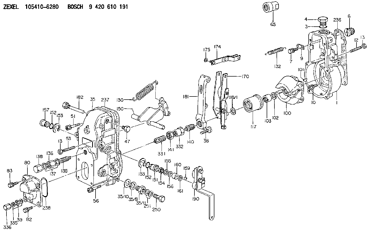
| 1. | [1] | 154000-6400 | GOVERNOR HOUSING |
| 3. | [1] | 029632-5070 | O-RING |
| 4. | [1] | 154007-2900 | CAPSULE |
| 6. | [1] | 154007-0200 | ADAPTOR |
| 7. | [1] | 020018-1840 | BLEEDER SCREW M8P1.25L18 |
| 9. | [1] | 154350-1900 | PLATE |
| 10. | [6] | 029010-6810 | BLEEDER SCREW |
| 12. | [1] | 154010-0100 | FLAT-HEAD SCREW |
| 13. | [2] | 154011-0100 | HEXAGON NUT |
| 13. | [2] | 154011-0100 | HEXAGON NUT |
| 35. | [1] | 154500-7520 | GOVERNOR COVER |
| 35/8. | [1] | 014110-3440 | LOCKING WASHER |
| 35/10. | [1] | 026516-2040 | GASKET D19.9&16.2T1 |
| 35/11. | [1] | 154316-6600 | ADAPTOR |
| 38. | [1] | 154031-3000 | FLAT-HEAD SCREW |
| 39. | [1] | 139206-0600 | UNION NUT |
| 47. | [1] | 154036-0300 | CAPSULE |
| 51. | [2] | 020106-5040 | BLEEDER SCREW |
| 53. | [1] | 154010-0300 | FLAT-HEAD SCREW |
| 56. | [4] | 020106-3840 | BLEEDER SCREW |
| 65. | [1] | 154050-1720 | STOPPING DEVICE |
| 80. | [1] | 154063-5100 | COVER |
| 82. | [2] | 029020-6210 | BLEEDER SCREW |
| 83. | [2] | 020006-1640 | BLEEDER SCREW M6P1L16 4T |
| 100. | [1] | 154100-9720 | FLYWEIGHT ASSEMBLY |
| 101. | [1] | 025803-1610 | WOODRUFF KEY |
| 102. | [1] | 029321-2020 | LOCKING WASHER |
| 103. | [1] | 029231-2030 | UNION NUT |
| 117. | [1] | 154123-0120 | SLIDING PIECE |
| 118/1. | [0] | 029311-0010 | SHIM D14&10.1T0.2 |
| 118/1. | [0] | 029311-0180 | SHIM D14&10.1T0.3 |
| 118/1. | [0] | 029311-0190 | SHIM D14&10.1T0.40 |
| 118/1. | [0] | 029311-0210 | SHIM D14&10.1T1 |
| 118/1. | [0] | 139410-0000 | SHIM D14.0&10.1T0.5 |
| 118/1. | [0] | 139410-0100 | SHIM D14.0&10.1T1.5 |
| 118/1. | [0] | 139410-3000 | SHIM D14&10.1T2.0 |
| 118/1. | [0] | 139410-3100 | SHIM D14&10.1T3.0 |
| 118/1. | [0] | 139410-3200 | SHIM D14&10.1T4.0 |
| 130. | [1] | 154150-2700 | GOVERNOR SPRING |
| 132. | [1] | 154154-0701 | COILED SPRING |
| 135. | [1] | 154158-0820 | HEADLESS SCREW |
| 136. | [1] | 154011-1700 | UNION NUT |
| 137. | [2] | 026512-1540 | GASKET D15.4&12.2T1.50 |
| 138. | [1] | 154159-1200 | CAP NUT |
| 140. | [1] | 154175-4620 | HEADLESS SCREW |
| 141. | [1] | 029201-6080 | UNION NUT |
| 150. | [1] | 154200-7220 | SWIVELLING LEVER |
| 151. | [1] | 154204-3000 | BUSHING |
| 152. | [2] | 029631-8020 | O-RING |
| 152. | [2] | 029631-8020 | O-RING |
| 153. | [2] | 016010-1640 | LOCKING WASHER |
| 153. | [2] | 016010-1640 | LOCKING WASHER |
| 154. | [1] | 139611-0000 | PACKING RING |
| 155. | [1] | 139411-0000 | SHIM |
| 156. | [0] | 029311-1070 | SHIM D16&11T0.5 |
| 157. | [1] | 154204-3100 | BUSHING |
| 159. | [1] | 025803-1310 | WOODRUFF KEY |
| 160. | [1] | 154206-2800 | BUSHING |
| 161. | [0] | 154206-0200 | PLAIN WASHER D19.5&11.2T1.0 |
| 170. | [1] | 154211-3820 | FORK LEVER |
| 174. | [1] | 154230-0120 | STRAP |
| 175. | [1] | 016010-0540 | LOCKING WASHER |
| 181. | [1] | 154236-1500 | TENSIONING LEVER |
| 182. | [1] | 154237-1100 | BEARING PIN |
| 190. | [1] | 154341-7820 | CONTROL LEVER |
| 236. | [1] | 154390-0000 | GASKET |
| 237. | [1] | 154390-0300 | GASKET |
| 238. | [1] | 029635-2020 | O-RING |
| 250. | [1] | 029731-2040 | EYE BOLT |
| 251. | [2] | 029341-2140 | GASKET |
| 331. | [1] | 154179-4020 | HEADLESS SCREW |
| 332. | [1] | 029201-6010 | UNION NUT |
| 335. | [2] | 026506-1040 | GASKET D9.9&6.2T1 |
| 336. | [1] | 154035-1600 | CAP NUT |
Cross reference number
Zexel num
Bosch num
Firm num
Name
105410-6280
GOVERNOR
K 14JB MECHANICAL GOVERNOR GOV RSV GOV
K 14JB MECHANICAL GOVERNOR GOV RSV GOV
Information:
1. Drain the coolant from the cooling system to a level below that of the water pump.2. Remove elbow (1).3. Remove bolts (4) that hold cover (2) to the water pump. Remove bolts (5) that hold elbow (3) to cover (2).4. Remove line (6).5. Remove cover (2). Remove elbow (3). 6. Remove four bolts (7).7. Remove nuts (8) and one bolt (not shown). Remove water pump.Install Water Pump
1. Put the water pump in position on the timing gear cover. Install nuts (8) and one bolt that hold the pump to the timing gear cover.2. Install four bolts (7). 3. Put clean engine oil or glycerin on O-ring seals (9). Install elbow (3). 4. Put cover (2) in position on the water pump. Install bolts (4) that hold the cover to the water pump and bolts (5) that hold elbow (3) to the cover.5. Install elbow (1).6. Install line (6).7. Fill the cooling system to the proper level. See the Operation & Maintenance Manual.Disassemble Water Pump
Start By:a. remove water pump 1. Remove O-ring seal (1) from adapter (2).2. Remove adapter (2) with a screwdriver. Remove the seal from the edge of adapter (2).3. Remove bolt (3) and washer. 4. Remove impeller (4) from the water pump housing with Tooling (A). 5. Remove seal assembly (5). Remove ring and seal (6). 6. Remove the bolt and washer that hold gear (7) on the water pump shaft.7. Remove gear (7) with Tooling (B).8. Remove bolts and retainer (9).9. Remove O-ring seal (8). 10. Remove shaft (10) and bearings as a unit.11. Remove bearing (11), spacer (12) and bearing (13) from shaft (10).12. Remove lip-type seal from the gear side of the water pump. Remove ring and seal from the impeller side of the water pump.Assemble Water Pump
1. Put clean engine oil or glycerin on the lip of seal (1). Install seal (1) as shown with Tooling (A). 2. Install bearing (4), spacer (3) and bearing (5) on shaft (2). Install shaft (2) in the pump housing. 3. Install retainer (7) and O-ring seal (8).4. Install gear (6). Install washer and bolt that hold gear (6) to shaft (2).
Clean water only is permitted for use as a lubricant for assistance at installation. Do not damage or put hands on the wear surface of the carbon ring or the ceramic ring. Install the ceramic ring with the smoothest face of the ring toward the carbon seal assembly.
5. Put ceramic ring (10) in position in the rubber seal (9). Use hand pressure and Tool (11) (which is with the replacement ring) to install the ceramic ring in the housing. 6. Remove the spring from seal assembly (12). Use hand pressure and Tool (11) (which is with the replacement ring) to install the seal assembly. Push seal assembly on the shaft until the seal faces make light contact. 7. Install spring (13) on the seal assembly and impeller (14) on the shaft. Install the bolt and washer on the shaft. Tighten the bolt to a