Information governor
BOSCH
F 019 Z1E 773
f019z1e773
ZEXEL
105410-6250
1054106250
Rating:
Scheme ###:
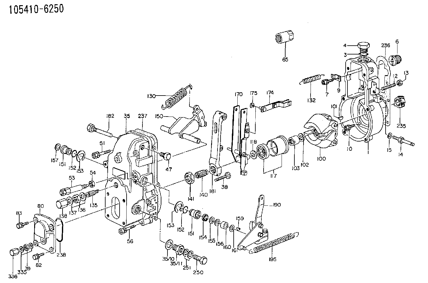
| 1. | [1] | 154000-6400 | GOVERNOR HOUSING |
| 3. | [1] | 029632-5070 | O-RING |
| 4. | [1] | 154007-2900 | CAPSULE |
| 6. | [1] | 154007-0200 | ADAPTOR |
| 7. | [1] | 020018-1840 | BLEEDER SCREW M8P1.25L18 |
| 9. | [1] | 154350-1900 | PLATE |
| 10. | [6] | 029010-6810 | BLEEDER SCREW |
| 12. | [1] | 154010-0100 | FLAT-HEAD SCREW |
| 13. | [1] | 154011-0100 | HEXAGON NUT |
| 14. | [1] | 154012-2220 | BLEEDER SCREW |
| 15. | [1] | 014110-8440 | LOCKING WASHER |
| 35. | [1] | 154500-5420 | GOVERNOR COVER |
| 35/7. | [1] | 154222-2700 | FLAT-HEAD SCREW |
| 35/8. | [1] | 014110-3440 | LOCKING WASHER |
| 35/10. | [1] | 026516-2040 | GASKET D19.9&16.2T1 |
| 35/11. | [1] | 154316-6600 | ADAPTOR |
| 38. | [1] | 154031-2400 | FLAT-HEAD SCREW |
| 39. | [1] | 139206-0600 | UNION NUT |
| 47. | [1] | 154036-0300 | CAPSULE |
| 51. | [2] | 020106-5040 | BLEEDER SCREW |
| 53. | [1] | 154010-5220 | HEADLESS SCREW |
| 54. | [1] | 154011-1900 | UNION NUT |
| 56. | [4] | 020106-3840 | BLEEDER SCREW |
| 65. | [1] | 155404-5700 | CAP |
| 80. | [1] | 154063-1400 | COVER |
| 82. | [2] | 029020-6210 | BLEEDER SCREW |
| 83. | [2] | 020006-1640 | BLEEDER SCREW M6P1L16 4T |
| 100. | [1] | 154100-9720 | FLYWEIGHT ASSEMBLY |
| 101. | [1] | 025803-1610 | WOODRUFF KEY |
| 102. | [1] | 029321-2020 | LOCKING WASHER |
| 103. | [1] | 029231-2030 | UNION NUT |
| 117. | [1] | 154123-0120 | SLIDING PIECE |
| 118/1. | [0] | 029311-0010 | SHIM D14&10.1T0.2 |
| 118/1. | [0] | 029311-0180 | SHIM D14&10.1T0.3 |
| 118/1. | [0] | 029311-0190 | SHIM D14&10.1T0.40 |
| 118/1. | [0] | 029311-0210 | SHIM D14&10.1T1 |
| 118/1. | [0] | 139410-0000 | SHIM D14.0&10.1T0.5 |
| 118/1. | [0] | 139410-0100 | SHIM D14.0&10.1T1.5 |
| 118/1. | [0] | 139410-3000 | SHIM D14&10.1T2.0 |
| 118/1. | [0] | 139410-3100 | SHIM D14&10.1T3.0 |
| 118/1. | [0] | 139410-3200 | SHIM D14&10.1T4.0 |
| 130. | [1] | 154150-2700 | GOVERNOR SPRING |
| 132. | [1] | 154154-0701 | COILED SPRING |
| 135. | [1] | 154158-0820 | HEADLESS SCREW |
| 136. | [1] | 154011-1700 | UNION NUT |
| 137. | [2] | 026512-1540 | GASKET D15.4&12.2T1.50 |
| 138. | [1] | 154159-1200 | CAP NUT |
| 140. | [1] | 154177-0920 | HEADLESS SCREW |
| 141. | [1] | 029201-6010 | UNION NUT |
| 150. | [1] | 154200-7220 | SWIVELLING LEVER |
| 151. | [1] | 154204-4300 | BUSHING |
| 151. | [1] | 154204-4300 | BUSHING |
| 152. | [2] | 029631-8020 | O-RING |
| 152. | [2] | 029631-8020 | O-RING |
| 153. | [2] | 016010-1640 | LOCKING WASHER |
| 153. | [2] | 016010-1640 | LOCKING WASHER |
| 154. | [1] | 139611-0000 | PACKING RING |
| 155. | [1] | 139411-0000 | SHIM |
| 156. | [0] | 029311-1070 | SHIM D16&11T0.5 |
| 157. | [1] | 154204-4400 | BUSHING |
| 159. | [1] | 025803-1310 | WOODRUFF KEY |
| 160. | [1] | 154206-2800 | BUSHING |
| 161. | [0] | 154206-0200 | PLAIN WASHER D19.5&11.2T1.0 |
| 170. | [1] | 154211-3820 | FORK LEVER |
| 174. | [1] | 154230-0120 | STRAP |
| 175. | [1] | 016010-0540 | LOCKING WASHER |
| 181. | [1] | 154236-1500 | TENSIONING LEVER |
| 182. | [1] | 154237-1100 | BEARING PIN |
| 190. | [1] | 154345-6120 | CONTROL LEVER |
| 195. | [1] | 154314-2500 | COILED SPRING |
| 235. | [1] | 155412-5200 | IMPELLER WHEEL |
| 236. | [1] | 154390-0000 | GASKET |
| 237. | [1] | 154390-0300 | GASKET |
| 238. | [1] | 029635-2020 | O-RING |
| 250. | [1] | 029731-2040 | EYE BOLT |
| 251. | [2] | 029341-2140 | GASKET |
| 335. | [2] | 026506-1040 | GASKET D9.9&6.2T1 |
| 336. | [1] | 154035-1600 | CAP NUT |
Include in #1:
101602-3430
as GOVERNOR
Cross reference number
Zexel num
Bosch num
Firm num
Name
105410-6250
F 019 Z1E 773
GOVERNOR
* K
* K
Information:
2. Remove three nuts and washers (1).3. Move Peec unit (2) out of the way. (If so equipped). 4. Remove elbows (5) and pipes (7).5. Remove fuel line brackets (4).6. Remove bolts (6). Remove cover (3). 7. Remove elbows (10). Remove adapters (8) and adapters (9) from the aftercooler core. Remove bolts (11). 8. Move aftercooler core (12) toward the front of the engine and use two people to remove the aftercooler core from the lower aftercooler housing. The weight of the aftercooler core is approximately 29 kg (65 lb). Remove the O-ring seals from the aftercooler core extensions.Install Aftercooler
1. Install O-ring seals (13) on the aftercooler core extensions. Put clean engine oil or glycerin on the seals.2. Use two people to put aftercooler core (12) into position in the lower aftercooler housing. The weight of the aftercooler core is approximately 29 kg (65 lb). 3. Install bolts (11). Put clean engine oil or glycerin on O-ring seal (14) and in bores (15) and (16). 4. Put clean engine oil or glycerin on O-ring seals (17) and adapters (8) and (9). Install adapters (8) and (9) in the aftercooler core. 5. Install elbows (10). 6. Put cover (3) into position on the engine. Install bolts (6).7. Install fuel injection line brackets (4). Tighten bolts (20) to a torque of 4.5 1.1 N m (40 10 lb in).8. Put clean engine oil or glycerin on pipes (7). Install pipes (7) and elbows (5).9. Fill the cooling system with coolant. See Operation & Maintenance Manual for the proper procedure and levels.
1. Install O-ring seals (13) on the aftercooler core extensions. Put clean engine oil or glycerin on the seals.2. Use two people to put aftercooler core (12) into position in the lower aftercooler housing. The weight of the aftercooler core is approximately 29 kg (65 lb). 3. Install bolts (11). Put clean engine oil or glycerin on O-ring seal (14) and in bores (15) and (16). 4. Put clean engine oil or glycerin on O-ring seals (17) and adapters (8) and (9). Install adapters (8) and (9) in the aftercooler core. 5. Install elbows (10). 6. Put cover (3) into position on the engine. Install bolts (6).7. Install fuel injection line brackets (4). Tighten bolts (20) to a torque of 4.5 1.1 N m (40 10 lb in).8. Put clean engine oil or glycerin on pipes (7). Install pipes (7) and elbows (5).9. Fill the cooling system with coolant. See Operation & Maintenance Manual for the proper procedure and levels.
Have questions with 105410-6250?
Group cross 105410-6250 ZEXEL
105410-6250
F 019 Z1E 773
GOVERNOR