Information governor
BOSCH
F 019 Z1E 770
f019z1e770
ZEXEL
105410-6120
1054106120
Rating:
Scheme ###:
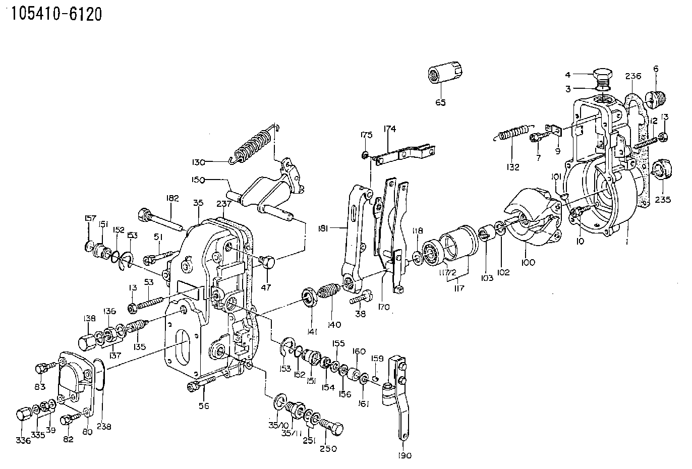
| 1. | [1] | 154000-6400 | GOVERNOR HOUSING |
| 3. | [1] | 029632-5070 | O-RING |
| 4. | [1] | 154007-2900 | CAPSULE |
| 6. | [1] | 154007-0200 | ADAPTOR |
| 7. | [1] | 020018-1840 | BLEEDER SCREW M8P1.25L18 |
| 9. | [1] | 154350-1900 | PLATE |
| 10. | [6] | 029010-6810 | BLEEDER SCREW |
| 12. | [1] | 154010-0100 | FLAT-HEAD SCREW |
| 13. | [2] | 154011-0100 | HEXAGON NUT |
| 13. | [2] | 154011-0100 | HEXAGON NUT |
| 35. | [1] | 154500-7320 | GOVERNOR COVER |
| 35/7. | [1] | 154222-2700 | FLAT-HEAD SCREW |
| 35/8. | [1] | 014110-3440 | LOCKING WASHER |
| 35/10. | [1] | 026516-2040 | GASKET D19.9&16.2T1 |
| 35/11. | [1] | 154316-6600 | ADAPTOR |
| 38. | [1] | 154031-2400 | FLAT-HEAD SCREW |
| 39. | [1] | 139206-0600 | UNION NUT |
| 47. | [1] | 154036-0300 | CAPSULE |
| 51. | [2] | 020106-5040 | BLEEDER SCREW |
| 53. | [1] | 154010-0300 | FLAT-HEAD SCREW |
| 56. | [4] | 020106-3840 | BLEEDER SCREW |
| 65. | [1] | 155404-5700 | CAP |
| 80. | [1] | 154063-1400 | COVER |
| 82. | [2] | 029020-6210 | BLEEDER SCREW |
| 83. | [2] | 020006-1640 | BLEEDER SCREW M6P1L16 4T |
| 100. | [1] | 154101-0020 | FLYWEIGHT ASSEMBLY |
| 101. | [1] | 025803-1610 | WOODRUFF KEY |
| 102. | [1] | 029321-2020 | LOCKING WASHER |
| 103. | [1] | 029231-2030 | UNION NUT |
| 117. | [1] | 154123-0120 | SLIDING PIECE |
| 118/1. | [0] | 029311-0010 | SHIM D14&10.1T0.2 |
| 118/1. | [0] | 029311-0180 | SHIM D14&10.1T0.3 |
| 118/1. | [0] | 029311-0190 | SHIM D14&10.1T0.40 |
| 118/1. | [0] | 029311-0210 | SHIM D14&10.1T1 |
| 118/1. | [0] | 139410-0000 | SHIM D14.0&10.1T0.5 |
| 118/1. | [0] | 139410-0100 | SHIM D14.0&10.1T1.5 |
| 118/1. | [0] | 139410-3000 | SHIM D14&10.1T2.0 |
| 118/1. | [0] | 139410-3100 | SHIM D14&10.1T3.0 |
| 118/1. | [0] | 139410-3200 | SHIM D14&10.1T4.0 |
| 130. | [1] | 154150-0400 | GOVERNOR SPRING |
| 132. | [1] | 154154-0701 | COILED SPRING |
| 135. | [1] | 154158-1320 | HEADLESS SCREW |
| 136. | [1] | 154011-1700 | UNION NUT |
| 137. | [2] | 026512-1540 | GASKET D15.4&12.2T1.50 |
| 138. | [1] | 154159-1200 | CAP NUT |
| 140. | [1] | 154177-1820 | HEADLESS SCREW |
| 141. | [1] | 029201-6010 | UNION NUT |
| 150. | [1] | 154200-6920 | SWIVELLING LEVER |
| 151. | [1] | 154204-3000 | BUSHING |
| 151. | [1] | 154204-3000 | BUSHING |
| 152. | [2] | 029631-8020 | O-RING |
| 152. | [2] | 029631-8020 | O-RING |
| 153. | [2] | 016010-1640 | LOCKING WASHER |
| 153. | [2] | 016010-1640 | LOCKING WASHER |
| 154. | [1] | 139611-0000 | PACKING RING |
| 155. | [1] | 139411-0000 | SHIM |
| 156. | [0] | 029311-1090 | SHIM D16&11T0.3 |
| 157. | [1] | 154204-3100 | BUSHING |
| 159. | [1] | 025803-1310 | WOODRUFF KEY |
| 160. | [1] | 154206-2800 | BUSHING |
| 161. | [0] | 154206-0200 | PLAIN WASHER D19.5&11.2T1.0 |
| 170. | [1] | 154210-7420 | FORK LEVER |
| 174. | [1] | 154230-0120 | STRAP |
| 175. | [1] | 016010-0540 | LOCKING WASHER |
| 181. | [1] | 154236-4100 | TENSIONING LEVER |
| 182. | [1] | 154237-1100 | BEARING PIN |
| 190. | [1] | 154341-8720 | CONTROL LEVER |
| 235. | [1] | 155412-5200 | IMPELLER WHEEL |
| 236. | [1] | 154390-0000 | GASKET |
| 237. | [1] | 154390-0300 | GASKET |
| 238. | [1] | 029635-2020 | O-RING |
| 250. | [1] | 029731-2040 | EYE BOLT |
| 251. | [2] | 029341-2140 | GASKET |
| 335. | [2] | 026506-1040 | GASKET D9.9&6.2T1 |
| 336. | [1] | 154035-1600 | CAP NUT |
Include in #1:
101602-3680
as GOVERNOR
Cross reference number
Zexel num
Bosch num
Firm num
Name
105410-6120
F 019 Z1E 770
GOVERNOR
* K
* K
Information:
Do not put oil on the bearings until the bearing clearance has been checked.1. Install bearings (1) in the connecting rods they were removed from. Make sure the tab in each bearing is in alignment with the notch in each connecting rod.2. Install bearings (2) in the cylinder block. Make sure the tab in each bearing is in alignment with the notch in the cylinder block. 3. Install pin (3) in the end of the crankshaft. Install the pin so that it extends a maximum of 6.4 mm (.252 in) above the surface. 4. Install the dowel in the crankshaft that puts gear (4) in the correct position. Install the dowel so that it extends 4.1 0.5 mm (.161 .020 in) above the surface of the crankshaft.5. Heat gear (4) to a maximum temperature of 233° C (451° F). Gear (4) must be installed on the crankshaft with the "V" timing mark toward the outside.6. Install gear (4) on the crankshaft. Make sure the notch in the gear is in alignment with the dowel on the crankshaft. The dimension from the rear face of the gear to the front face of the crankshaft must be 45.54 0.25 mm (1.793 .010 in). 7. Fasten Tooling (A) and a hoist to the crankshaft (5) as shown. Install the crankshaft in the engine. The weight of the crankshaft is approximately 131 kg (290 lb). 8. Make sure that "V" mark (6) on the crankshaft is in alignment with "V" mark (7) on the idler gear. The side of each thrust plate (8) with the words "BLOCK SIDE" must be installed with this side toward the cylinder block.9. Put clean oil on thrust plates (8). Install thrust plates (8) next to the center main bearings. Do not put oil on bearings (9) until the bearing clearances have been checked.10. Put bearings (9) in their original position in crankshaft main bearing caps (10).11. Check the crankshaft main bearing clearance with Plastigage as follows:a. Put a piece of Plastigage between the crankshaft bearing journal surface and bearing (9).b. Install the crankshaft main bearing caps (10) with the arrow on each cap toward the front of cylinder block. Each crankshaft main bearing cap has a number on the bottom surface and must be installed in the same position as the correct number on the left side of the cylinder block.c. Put 2P-2506 Thread Lubricant on the threads of the cap bolts. Install the cap bolts finger tight.d. Tighten the bolts on the tab end of the caps first to a torque of 258 14 N m (190 10 lb ft).e. Tighten the bolts on the other end of the caps to a torque of 258 14 N m (190 10 lb ft).
Do not use an impact wrench to tighten the bolts the additional 120 degrees.
f. Put a mark across the bolt head and cap. Tighten the bolts opposite the tab end of the cap
Do not use an impact wrench to tighten the bolts the additional 120 degrees.
f. Put a mark across the bolt head and cap. Tighten the bolts opposite the tab end of the cap
Have questions with 105410-6120?
Group cross 105410-6120 ZEXEL
105410-6120
F 019 Z1E 770
GOVERNOR