Information governor
BOSCH
F 019 Z1E 084
f019z1e084
ZEXEL
105410-6080
1054106080
ISUZU
1157204850
1157204850
Rating:
Scheme ###:
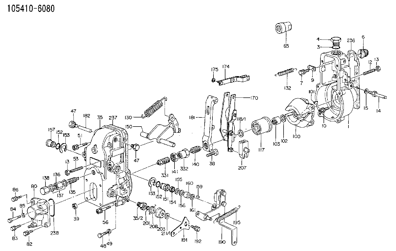
| 1. | [1] | 154000-6400 | GOVERNOR HOUSING |
| 3. | [1] | 029632-5070 | O-RING |
| 4. | [1] | 154007-2900 | CAPSULE |
| 6. | [1] | 154007-0200 | ADAPTOR |
| 7. | [1] | 020018-1840 | BLEEDER SCREW M8P1.25L18 |
| 9. | [1] | 154350-1900 | PLATE |
| 10. | [6] | 029010-6810 | BLEEDER SCREW |
| 12. | [1] | 154010-0100 | FLAT-HEAD SCREW |
| 13. | [2] | 154011-0100 | HEXAGON NUT |
| 13. | [2] | 154011-0100 | HEXAGON NUT |
| 14. | [1] | 154012-1500 | BLEEDER SCREW |
| 15. | [1] | 014110-8440 | LOCKING WASHER |
| 35. | [1] | 154500-3720 | GOVERNOR COVER |
| 35/2. | [1] | 154321-0400 | BUSHING |
| 38. | [1] | 154031-0100 | FLAT-HEAD SCREW |
| 39. | [1] | 013020-6020 | UNION NUT M6P1H5 |
| 47. | [2] | 154036-0300 | CAPSULE |
| 47. | [2] | 154036-0300 | CAPSULE |
| 48. | [1] | 154037-0700 | BLEEDER SCREW |
| 49. | [1] | 154038-0200 | HEXAGON NUT |
| 51. | [2] | 020106-5040 | BLEEDER SCREW |
| 53. | [1] | 154010-0200 | FLAT-HEAD SCREW |
| 56. | [4] | 020106-3840 | BLEEDER SCREW |
| 65. | [1] | 155404-0200 | CAP |
| 80. | [1] | 154063-1220 | COVER |
| 82. | [1] | 020006-1640 | BLEEDER SCREW M6P1L16 4T |
| 83. | [1] | 020006-1640 | BLEEDER SCREW M6P1L16 4T |
| 84. | [1] | 029020-6250 | BLEEDER SCREW |
| 85. | [1] | 014110-6440 | LOCKING WASHER |
| 86. | [1] | 020006-1640 | BLEEDER SCREW M6P1L16 4T |
| 100. | [1] | 154101-0020 | FLYWEIGHT ASSEMBLY |
| 101. | [1] | 025803-1610 | WOODRUFF KEY |
| 102. | [1] | 029321-2020 | LOCKING WASHER |
| 103. | [1] | 029231-2030 | UNION NUT |
| 117. | [1] | 154123-0120 | SLIDING PIECE |
| 118/1. | [0] | 029311-0010 | SHIM D14&10.1T0.2 |
| 118/1. | [0] | 029311-0180 | SHIM D14&10.1T0.3 |
| 118/1. | [0] | 029311-0190 | SHIM D14&10.1T0.40 |
| 118/1. | [0] | 029311-0210 | SHIM D14&10.1T1 |
| 118/1. | [0] | 139410-0000 | SHIM D14.0&10.1T0.5 |
| 118/1. | [0] | 139410-0100 | SHIM D14.0&10.1T1.5 |
| 118/1. | [0] | 139410-3000 | SHIM D14&10.1T2.0 |
| 118/1. | [0] | 139410-3100 | SHIM D14&10.1T3.0 |
| 118/1. | [0] | 139410-3200 | SHIM D14&10.1T4.0 |
| 130. | [1] | 154150-7700 | GOVERNOR SPRING |
| 132. | [1] | 154154-0800 | COILED SPRING |
| 135. | [1] | 154157-0120 | HEADLESS SCREW |
| 136. | [1] | 029201-2030 | UNION NUT M12P1.0H4 |
| 137. | [2] | 026512-1540 | GASKET D15.4&12.2T1.50 |
| 138. | [1] | 154159-1200 | CAP NUT |
| 140. | [1] | 154178-1820 | HEADLESS SCREW |
| 141. | [1] | 029201-6080 | UNION NUT |
| 150. | [1] | 154200-7220 | SWIVELLING LEVER |
| 151. | [1] | 154204-4300 | BUSHING |
| 152. | [2] | 029631-8020 | O-RING |
| 152. | [2] | 029631-8020 | O-RING |
| 153. | [2] | 016010-1640 | LOCKING WASHER |
| 153. | [2] | 016010-1640 | LOCKING WASHER |
| 154. | [1] | 139611-0000 | PACKING RING |
| 155. | [1] | 139411-0000 | SHIM |
| 156. | [0] | 029311-1070 | SHIM D16&11T0.5 |
| 157. | [1] | 154204-4400 | BUSHING |
| 159. | [1] | 025803-1310 | WOODRUFF KEY |
| 160. | [1] | 154206-2800 | BUSHING |
| 161. | [0] | 154206-0200 | PLAIN WASHER D19.5&11.2T1.0 |
| 170. | [1] | 154210-7420 | FORK LEVER |
| 174. | [1] | 154230-3920 | STRAP |
| 175. | [1] | 016010-0540 | LOCKING WASHER |
| 181. | [1] | 154236-1500 | TENSIONING LEVER |
| 182. | [1] | 154237-0100 | BEARING PIN |
| 190. | [1] | 154342-1420 | CONTROL LEVER |
| 191. | [1] | 154307-0100 | CONTROL LEVER |
| 192. | [1] | 020006-1640 | BLEEDER SCREW M6P1L16 4T |
| 195. | [1] | 154314-0200 | COILED SPRING |
| 201. | [1] | 029631-0030 | O-RING &9.8W2.3 |
| 203. | [1] | 154322-0100 | CAP |
| 207. | [1] | 154326-5120 | CONTROL LEVER |
| 208. | [1] | 154327-7300 | COILED SPRING |
| 211/1. | [0] | 029311-0520 | SHIM D20.8&10.3T0.2 |
| 211/1. | [0] | 029311-0530 | SHIM D20.8&10.3T0.25 |
| 211/1. | [0] | 029311-0540 | SHIM D20.8&10.3T0.3 |
| 211/1. | [0] | 029311-0550 | SHIM D20.8&10.3T0.35 |
| 211/1. | [0] | 029311-0560 | SHIM D20.8&10.3T0.4 |
| 211/1. | [0] | 029311-0570 | SHIM D20.8&10.3T0.5 |
| 236. | [1] | 154390-0000 | GASKET |
| 237. | [1] | 154390-0300 | GASKET |
| 238. | [1] | 029635-2020 | O-RING |
| 331. | [1] | 154172-4120 | HEADLESS SCREW |
| 332. | [1] | 029201-6010 | UNION NUT |
Cross reference number
Zexel num
Bosch num
Firm num
Name
105410-6080
1157204850 ISUZU
GOVERNOR
K 14JB MECHANICAL GOVERNOR GOV RSV GOV
K 14JB MECHANICAL GOVERNOR GOV RSV GOV
Information:
Start By:a. remove exhaust manifoldsb. remove push rods and valve liftersc. remove water temperature regulators Put protection caps on all fuel openings. 1. Remove the bolts and valve cover base (1) from the cylinder head assembly.2. Disconnect hose (2) from the cylinder head assembly. 3. Put identification marks on wires (3), and disconnect them from the sending unit. 4. Remove six head bolts (4), and install Tooling (A). 5. Fasten a hoist to Tooling (A), and remove the remainder of the bolts that fasten the head assembly.6. Remove cylinder head assembly (5). The weight of the head assembly is 102 kg (224 lb). A new spacer plate gasket must be installed when the cylinder head is removed. See Remove & Install Spacer Plate.Install Cylinder Head Assemblies
1. Thoroughly clean the spacer plates and bottom surface of the cylinder head assemblies. Install a new head gasket and seals. Do not use any adhesives. A new spacer plate gasket must be installed when the cylinder head assembly is removed. See Remove And Install Spacer Plate. 2. Fasten Tooling (A) to the cylinder head assembly, and put cylinder head assembly (1) into position on the spacer plate. The use of guide bolts will help put the cylinder head assembly in alignment with the spacer plate.
(1) Large bolts (3/4 in). Put 6V-4876 Molycoat Paste Lubricant on the threads and between washer and underside of the cylinder head bolts. (2) Small bolts (3/8 in). See Step 3h.3. Install cylinder head bolts and washers. Tighten the bolts in the following sequence:a. Tighten bolts 1 through 10 in number sequence to 270 25 N m (200 20 lb ft)b. Tighten bolts 1 through 10 in number sequence to 470 20 N m (345 15 lb ft)c. Tighten bolts 1 through 10 in number sequence again to 470 20 N m (345 15 lb ft).d. Install the rocker arm shafts for the engine valves.e. Tighten bolts 11 through 18 in number sequence to 270 25 N m (200 20 lb ft).f. Tighten bolts 11 through 18 in number sequence to 450 20 N m (330 15 lb ft).g. Tighten bolts 11 through 18 in number sequence again to 450 20 N m (330 15 lb ft).h. Tighten the nine small bolts (2) to 45 7 N m (33 5 lb ft). 4. Connect hose (3) and the wire assembly to the cylinder head. 5. Install valve cover base (2) to the cylinder head. Tighten the bolts to a torque of 14 4 N m (10 3 lb ft) and the sequence as shown.End By:a. install water temperature regulatorsb. install push rods and valve liftersc. install exhaust manifolds