Information governor
BOSCH
F 019 Z1E 081
f019z1e081
ZEXEL
105410-6020
1054106020
ISUZU
1157204780
1157204780
Rating:
Scheme ###:
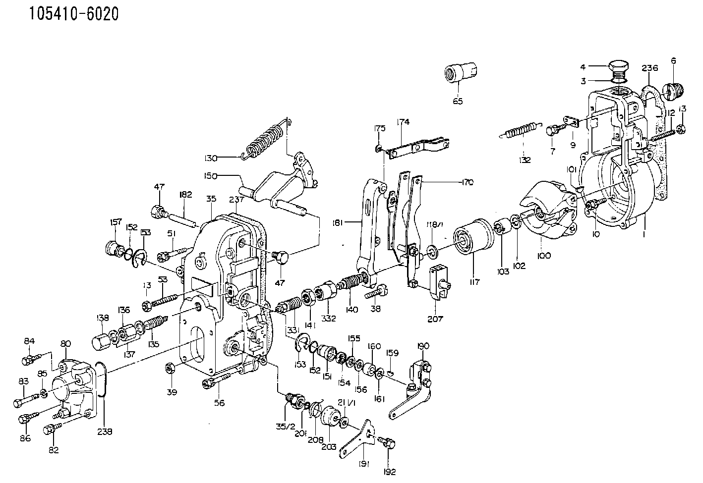
| 1. | [1] | 154000-6400 | GOVERNOR HOUSING |
| 3. | [1] | 029632-5070 | O-RING |
| 4. | [1] | 154007-2900 | CAPSULE |
| 6. | [1] | 154007-0200 | ADAPTOR |
| 7. | [1] | 020018-1840 | BLEEDER SCREW M8P1.25L18 |
| 9. | [1] | 154350-1900 | PLATE |
| 10. | [6] | 029010-6810 | BLEEDER SCREW |
| 12. | [1] | 154010-0100 | FLAT-HEAD SCREW |
| 13. | [2] | 154011-0100 | HEXAGON NUT |
| 13. | [2] | 154011-0100 | HEXAGON NUT |
| 14. | [1] | 154012-1500 | BLEEDER SCREW |
| 15. | [1] | 014110-8440 | LOCKING WASHER |
| 35. | [1] | 154500-3720 | GOVERNOR COVER |
| 35/2. | [1] | 154321-0400 | BUSHING |
| 38. | [1] | 154031-0100 | FLAT-HEAD SCREW |
| 39. | [1] | 013020-6020 | UNION NUT M6P1H5 |
| 47. | [2] | 154036-0300 | CAPSULE |
| 47. | [2] | 154036-0300 | CAPSULE |
| 48. | [1] | 154037-0700 | BLEEDER SCREW |
| 49. | [1] | 154038-0200 | HEXAGON NUT |
| 51. | [2] | 020106-5040 | BLEEDER SCREW |
| 53. | [1] | 154010-0200 | FLAT-HEAD SCREW |
| 56. | [4] | 020106-3840 | BLEEDER SCREW |
| 65. | [1] | 155404-0200 | CAP |
| 80. | [1] | 154063-0600 | COVER |
| 82. | [1] | 020006-1640 | BLEEDER SCREW M6P1L16 4T |
| 83. | [1] | 020006-1640 | BLEEDER SCREW M6P1L16 4T |
| 84. | [1] | 029020-6250 | BLEEDER SCREW |
| 85. | [1] | 014110-6440 | LOCKING WASHER |
| 86. | [1] | 020006-1640 | BLEEDER SCREW M6P1L16 4T |
| 100. | [1] | 154100-4020 | FLYWEIGHT ASSEMBLY |
| 101. | [1] | 025803-1610 | WOODRUFF KEY |
| 102. | [1] | 029321-2020 | LOCKING WASHER |
| 103. | [1] | 029231-2030 | UNION NUT |
| 117. | [1] | 154123-0120 | SLIDING PIECE |
| 118/1. | [0] | 029311-0010 | SHIM D14&10.1T0.2 |
| 118/1. | [0] | 029311-0180 | SHIM D14&10.1T0.3 |
| 118/1. | [0] | 029311-0190 | SHIM D14&10.1T0.40 |
| 118/1. | [0] | 029311-0210 | SHIM D14&10.1T1 |
| 118/1. | [0] | 139410-0000 | SHIM D14.0&10.1T0.5 |
| 118/1. | [0] | 139410-0100 | SHIM D14.0&10.1T1.5 |
| 118/1. | [0] | 139410-3000 | SHIM D14&10.1T2.0 |
| 118/1. | [0] | 139410-3100 | SHIM D14&10.1T3.0 |
| 118/1. | [0] | 139410-3200 | SHIM D14&10.1T4.0 |
| 130. | [1] | 154150-0400 | GOVERNOR SPRING |
| 132. | [1] | 154154-0701 | COILED SPRING |
| 135. | [1] | 154158-0920 | HEADLESS SCREW |
| 136. | [1] | 154011-1700 | UNION NUT |
| 137. | [2] | 026512-1540 | GASKET D15.4&12.2T1.50 |
| 138. | [1] | 154159-1200 | CAP NUT |
| 140. | [1] | 154178-9220 | HEADLESS SCREW |
| 141. | [1] | 029201-6080 | UNION NUT |
| 150. | [1] | 154200-6920 | SWIVELLING LEVER |
| 151. | [1] | 154204-4300 | BUSHING |
| 152. | [2] | 029631-8020 | O-RING |
| 152. | [2] | 029631-8020 | O-RING |
| 153. | [2] | 016010-1640 | LOCKING WASHER |
| 153. | [2] | 016010-1640 | LOCKING WASHER |
| 154. | [1] | 139611-0000 | PACKING RING |
| 155. | [1] | 139411-0000 | SHIM |
| 156. | [0] | 029311-1070 | SHIM D16&11T0.5 |
| 157. | [1] | 154204-4400 | BUSHING |
| 159. | [1] | 025803-1310 | WOODRUFF KEY |
| 160. | [1] | 154206-2800 | BUSHING |
| 161. | [0] | 154206-0200 | PLAIN WASHER D19.5&11.2T1.0 |
| 170. | [1] | 154210-7420 | FORK LEVER |
| 174. | [1] | 154230-3920 | STRAP |
| 175. | [1] | 016010-0540 | LOCKING WASHER |
| 181. | [1] | 154236-4100 | TENSIONING LEVER |
| 182. | [1] | 154237-0100 | BEARING PIN |
| 190. | [1] | 154342-1420 | CONTROL LEVER |
| 191. | [1] | 154307-0100 | CONTROL LEVER |
| 192. | [1] | 020006-1640 | BLEEDER SCREW M6P1L16 4T |
| 195. | [1] | 154314-0200 | COILED SPRING |
| 201. | [1] | 029631-0030 | O-RING &9.8W2.3 |
| 203. | [1] | 154322-0100 | CAP |
| 207. | [1] | 154326-5120 | CONTROL LEVER |
| 208. | [1] | 154327-7300 | COILED SPRING |
| 211/1. | [0] | 029311-0520 | SHIM D20.8&10.3T0.2 |
| 211/1. | [0] | 029311-0530 | SHIM D20.8&10.3T0.25 |
| 211/1. | [0] | 029311-0540 | SHIM D20.8&10.3T0.3 |
| 211/1. | [0] | 029311-0550 | SHIM D20.8&10.3T0.35 |
| 211/1. | [0] | 029311-0560 | SHIM D20.8&10.3T0.4 |
| 211/1. | [0] | 029311-0570 | SHIM D20.8&10.3T0.5 |
| 236. | [1] | 154390-0000 | GASKET |
| 237. | [1] | 154390-0300 | GASKET |
| 238. | [1] | 029635-2020 | O-RING |
| 331. | [1] | 154172-3920 | HEADLESS SCREW |
| 332. | [1] | 029201-6010 | UNION NUT |
Include in #1:
101602-0821
as GOVERNOR
Cross reference number
Zexel num
Bosch num
Firm num
Name
105410-6020
1157204780 ISUZU
GOVERNOR
K 14JB MECHANICAL GOVERNOR GOV RSV GOV
K 14JB MECHANICAL GOVERNOR GOV RSV GOV
Information:
Start By:a. remove timing gear coverb. remove push rods and valve lifters 1. Remove air compressor outlet hose (1). (Not applicable).2. Remove air compressor air inlet tube (3). (Not applicable).3. Remove air compressor coolant outlet tube (4). (Not applicable)4. Remove turbocharger oil return tube (2). 5. Use Tooling (A) to remove studs (5).6. Turn the flywheel with Tool (B), and remove each bolt (6) as it becomes accessible.7. Turn the flywheel with Tool (B) until the "V" marks on the front timing gears are in alignment.8. Install Tooling (C) through the holes for studs (5) into camshaft rear gear (7).
Tooling (C) must be used to prevent the loss of rear balance weight timing and to keep the camshaft rear gear in place when the camshaft is removed.
9. Tighten Tooling (C) evenly to remove the camshaft rear gear from the camshaft. 10. Remove thrust plate (8).
Be careful not to damage the camshaft bearings. Do not pry the camshaft out of the cylinder block. If resistance to camshaft removal occurs, turn the camshaft so the lobes will align the bearing journals with the camshaft bearing bores.
11. Carefully remove the camshaft and gear (9) from the cylinder block.12. If removal of the camshaft gear is necessary, place the camshaft and gear in a hydraulic press. Place Tool (D) over the camshaft, and press against it to remove the camshaft from the gear.
Be careful not to scratch or mar the finished surfaces of the camshaft.
13. Remove the key from the camshaft.14. If dowel removal is necessary, use Tool (E) to remove the dowel.Install Camshaft
1. Install the key in the camshaft. Be sure the key is seated in the camshaft.2. Install the pin in the rear of the camshaft. Install the pin to a height of 8.51 to 9.01 mm (.335 to .355 in).3. Heat the camshaft drive gear to a maximum temperature of 204° C (400° F), align the groove in the drive gear with the key in the camshaft, and install the camshaft drive gear with the timing marks away from the camshaft.4. Put clean engine oil on the camshaft bearing journals and lobes.5. Carefully install the camshaft into the cylinder block. Do not force the camshaft into position. If resistance to camshaft installation occurs, turn the camshaft so the lobes will align the bearing journals with the camshaft bearing bores. 6. Align the "V" marks on camshaft drive gear (2) and idler gear (3).7. Install thrust plate (1) to hold the camshaft and camshaft drive gear (2) in the cylinder block. 8. Loosen the bolts Tool (B) that hold camshaft rear gear (5) so camshaft rear gear (5) will engage the dowel on the rear of the camshaft.9. After the dowel is engaged, remove Tool (B), and install bolts (4).10. Use Tool (A) to turn the flywheel, and install each of four bolts (4). Tighten bolts (4) to a torque of 23 to 31 N m (17 to 23 lb ft).11. Put 5P-3413 Pipe Sealant with "Teflon" on the