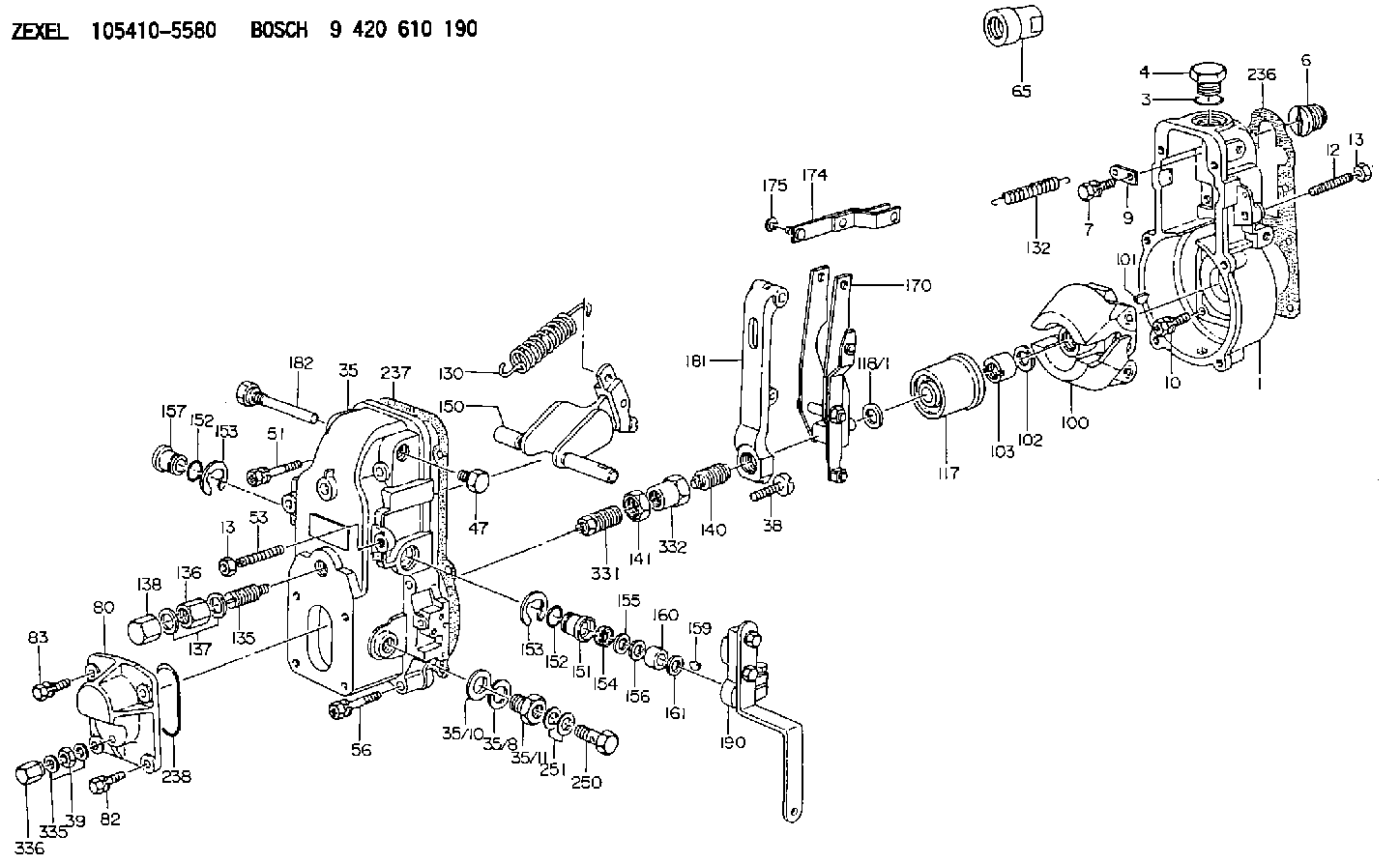
Information governor
BOSCH
9 420 610 190
9420610190
ZEXEL
105410-5580
1054105580
Rating:
Scheme ###:
| 1. | [1] | 154000-6400 | GOVERNOR HOUSING |
| 3. | [1] | 029632-5070 | O-RING |
| 4. | [1] | 154007-2900 | CAPSULE |
| 6. | [1] | 154007-0200 | ADAPTOR |
| 7. | [1] | 020018-1840 | BLEEDER SCREW M8P1.25L18 |
| 9. | [1] | 154350-1900 | PLATE |
| 10. | [6] | 029010-6810 | BLEEDER SCREW |
| 12. | [1] | 154010-0100 | FLAT-HEAD SCREW |
| 13. | [2] | 154011-0100 | HEXAGON NUT |
| 13. | [2] | 154011-0100 | HEXAGON NUT |
| 35. | [1] | 154500-7520 | GOVERNOR COVER |
| 35/8. | [1] | 014110-3440 | LOCKING WASHER |
| 35/10. | [1] | 026516-2040 | GASKET D19.9&16.2T1 |
| 35/11. | [1] | 154316-6600 | ADAPTOR |
| 38. | [1] | 154031-3000 | FLAT-HEAD SCREW |
| 39. | [1] | 139206-0600 | UNION NUT |
| 47. | [1] | 154036-0300 | CAPSULE |
| 51. | [2] | 020106-5040 | BLEEDER SCREW |
| 53. | [1] | 154010-0300 | FLAT-HEAD SCREW |
| 56. | [4] | 020106-3840 | BLEEDER SCREW |
| 65. | [1] | 154050-1720 | STOPPING DEVICE |
| 80. | [1] | 154063-5100 | COVER |
| 82. | [2] | 029020-6210 | BLEEDER SCREW |
| 83. | [2] | 020006-1640 | BLEEDER SCREW M6P1L16 4T |
| 100. | [1] | 154100-9720 | FLYWEIGHT ASSEMBLY |
| 101. | [1] | 025803-1610 | WOODRUFF KEY |
| 102. | [1] | 029321-2020 | LOCKING WASHER |
| 103. | [1] | 029231-2030 | UNION NUT |
| 117. | [1] | 154123-0120 | SLIDING PIECE |
| 118/1. | [0] | 029311-0010 | SHIM D14&10.1T0.2 |
| 118/1. | [0] | 029311-0180 | SHIM D14&10.1T0.3 |
| 118/1. | [0] | 029311-0190 | SHIM D14&10.1T0.40 |
| 118/1. | [0] | 029311-0210 | SHIM D14&10.1T1 |
| 118/1. | [0] | 139410-0000 | SHIM D14.0&10.1T0.5 |
| 118/1. | [0] | 139410-0100 | SHIM D14.0&10.1T1.5 |
| 118/1. | [0] | 139410-3000 | SHIM D14&10.1T2.0 |
| 118/1. | [0] | 139410-3100 | SHIM D14&10.1T3.0 |
| 118/1. | [0] | 139410-3200 | SHIM D14&10.1T4.0 |
| 130. | [1] | 154150-2700 | GOVERNOR SPRING |
| 132. | [1] | 154154-0701 | COILED SPRING |
| 135. | [1] | 154158-0820 | HEADLESS SCREW |
| 136. | [1] | 154011-1700 | UNION NUT |
| 137. | [2] | 026512-1540 | GASKET D15.4&12.2T1.50 |
| 138. | [1] | 154159-1200 | CAP NUT |
| 140. | [1] | 154185-0620 | HEADLESS SCREW |
| 141. | [1] | 029201-6080 | UNION NUT |
| 150. | [1] | 154200-7220 | SWIVELLING LEVER |
| 151. | [1] | 154204-3000 | BUSHING |
| 152. | [2] | 029631-8020 | O-RING |
| 152. | [2] | 029631-8020 | O-RING |
| 153. | [2] | 016010-1640 | LOCKING WASHER |
| 153. | [2] | 016010-1640 | LOCKING WASHER |
| 154. | [1] | 139611-0000 | PACKING RING |
| 155. | [1] | 139411-0000 | SHIM |
| 156. | [0] | 029311-1070 | SHIM D16&11T0.5 |
| 157. | [1] | 154204-3100 | BUSHING |
| 159. | [1] | 025803-1310 | WOODRUFF KEY |
| 160. | [1] | 154206-2800 | BUSHING |
| 161. | [0] | 154206-0200 | PLAIN WASHER D19.5&11.2T1.0 |
| 170. | [1] | 154211-3820 | FORK LEVER |
| 174. | [1] | 154230-0120 | STRAP |
| 175. | [1] | 016010-0540 | LOCKING WASHER |
| 181. | [1] | 154236-1500 | TENSIONING LEVER |
| 182. | [1] | 154237-1100 | BEARING PIN |
| 190. | [1] | 154341-7820 | CONTROL LEVER |
| 235. | [1] | 155412-5200 | IMPELLER WHEEL |
| 236. | [1] | 154390-0000 | GASKET |
| 237. | [1] | 154390-0300 | GASKET |
| 238. | [1] | 029635-2020 | O-RING |
| 250. | [1] | 029731-2040 | EYE BOLT |
| 251. | [2] | 029341-2140 | GASKET |
| 331. | [1] | 154179-0620 | HEADLESS SCREW |
| 332. | [1] | 029201-6010 | UNION NUT |
| 335. | [2] | 026506-1040 | GASKET D9.9&6.2T1 |
| 336. | [1] | 154035-1600 | CAP NUT |
Include in #1:
101602-3210
as GOVERNOR
Cross reference number
Zexel num
Bosch num
Firm num
Name
Information:
Start By:a. remove all turbochargersb. remove crankshaft rear seal and wear sleeve 1. Disconnect connector (1). 2. Attach Tool (A) and fasten a hoist.3. Remove four bolts (3) and stack (2). The weight of the stack and hardware is 45 kg (100 lb). 4. Remove hose clamp (6).5. Remove five bolts (5) and support (4).6. Repeat Steps 4 and 5 for the other side of the engine. 7. Remove six bolts (7) that connect oil pan (8) to flywheel housing (9). Loosen the rest of the bolts that hold the oil pan in position. 8. Attach Tool (A) to the flywheel housing and a hoist. 9. Lift the end of the engine enough so a 1/2 in. Hardened Washer (10) can be installed on each side of the engine between the oil pan and the cylinder block.10. Install blocks under the oil pan to support the engine when the flywheel housing is removed. Lower the engine onto the blocks. 11. Remove twenty one bolts (11) and flywheel housing (9). The weight of the flywheel housing is 91 kg (200 lb).Install Flywheel Housing
1. Install two 1/2 -13 NC × 4 in. Long Guide Bolts in the cylinder block. Make sure gasket (12) is in position. The cylinder block, both sides of gasket (12) and the surface of the flywheel housing that makes contact with the gasket must not have any oil, fuel, water or gasket adhesive on them when the flywheel housing is installed on the engine.2. Install Tool (A) on the flywheel housing. Install flywheel housing (9) on the engine. The weight of the flywheel housing is approximately 91 kg (200 lb). Leave Tool (A) attached.
Torque Sequence Put 9S-3263 Thread Lock on bolts (17) through (20) before installation.3. Install the bolts that hold the flywheel housing in place.4. Use the following procedure to tighten the bolts: a. Tighten bolts 1 through 8 in number sequence to 136 14 N m (100 10 lb ft).b. Tighten bolts 9 through 20 in number sequence to 55 7 N m (41 5 lb ft).c. Again, tighten bolts 1 through 8 in number sequence to 136 14 N m (100 10 lb ft).d. Again, tighten bolts 9 through 20 in number sequence to 55 7 N m (41 5 lb ft). If a new gasket is installed, cut the ends of the gasket so it is even with the bottom of the cylinder block.5. Use Tool (A) and a hoist to lift the flywheel housing and engine enough so that the washers between the oil pan and the cylinder block can be removed. 6. Tighten the bolts that hold the oil pan to the cylinder block. Install six bolts (7) that hold oil pan (8) to flywheel housing (9). 7. Install support (4) with five bolts (5). Install clamp (6) to a torque of 7.0 1.5 N m (5 1 lb ft).8. Repeat Step (7) for the other side of the engine.