Information governor
BOSCH
F 019 Z1E 765
f019z1e765
ZEXEL
105410-5450
1054105450
Rating:
Scheme ###:
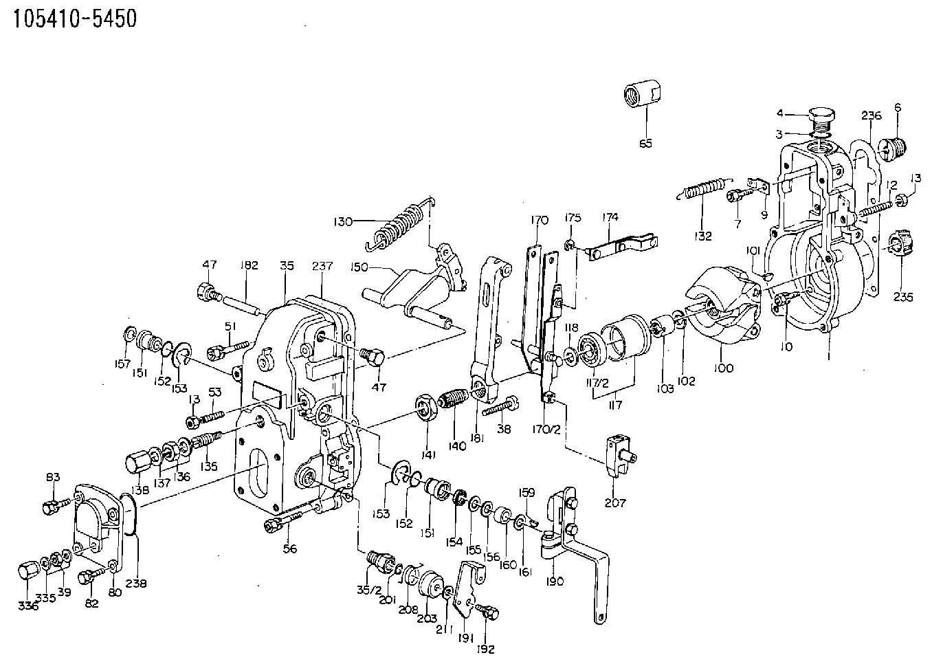
| 1. | [1] | 154000-6400 | GOVERNOR HOUSING |
| 3. | [1] | 029632-5070 | O-RING |
| 4. | [1] | 154007-2900 | CAPSULE |
| 6. | [1] | 154007-0200 | ADAPTOR |
| 7. | [1] | 020018-1840 | BLEEDER SCREW M8P1.25L18 |
| 9. | [1] | 154350-1900 | PLATE |
| 10. | [6] | 029010-6810 | BLEEDER SCREW |
| 12. | [1] | 154010-1100 | FLAT-HEAD SCREW |
| 13. | [2] | 154011-0100 | HEXAGON NUT |
| 13. | [2] | 154011-0100 | HEXAGON NUT |
| 35. | [1] | 154500-3020 | GOVERNOR COVER |
| 35/2. | [1] | 154321-0400 | BUSHING |
| 38. | [1] | 154031-2400 | FLAT-HEAD SCREW |
| 39. | [1] | 139206-0600 | UNION NUT |
| 47. | [1] | 154036-0300 | CAPSULE |
| 47. | [1] | 154036-0300 | CAPSULE |
| 51. | [2] | 020106-5040 | BLEEDER SCREW |
| 53. | [1] | 154010-0200 | FLAT-HEAD SCREW |
| 56. | [4] | 020106-3840 | BLEEDER SCREW |
| 65. | [1] | 155404-3700 | CAP |
| 80. | [1] | 154063-1400 | COVER |
| 82. | [2] | 029020-6210 | BLEEDER SCREW |
| 83. | [2] | 020006-1640 | BLEEDER SCREW M6P1L16 4T |
| 100. | [1] | 154100-9720 | FLYWEIGHT ASSEMBLY |
| 101. | [1] | 025803-1610 | WOODRUFF KEY |
| 102. | [1] | 029321-2020 | LOCKING WASHER |
| 103. | [1] | 029231-2030 | UNION NUT |
| 117. | [1] | 154123-0120 | SLIDING PIECE |
| 118/1. | [0] | 029311-0010 | SHIM D14&10.1T0.2 |
| 118/1. | [0] | 029311-0180 | SHIM D14&10.1T0.3 |
| 118/1. | [0] | 029311-0190 | SHIM D14&10.1T0.40 |
| 118/1. | [0] | 029311-0210 | SHIM D14&10.1T1 |
| 118/1. | [0] | 139410-0000 | SHIM D14.0&10.1T0.5 |
| 118/1. | [0] | 139410-0100 | SHIM D14.0&10.1T1.5 |
| 118/1. | [0] | 139410-3000 | SHIM D14&10.1T2.0 |
| 118/1. | [0] | 139410-3100 | SHIM D14&10.1T3.0 |
| 118/1. | [0] | 139410-3200 | SHIM D14&10.1T4.0 |
| 130. | [1] | 154150-2700 | GOVERNOR SPRING |
| 132. | [1] | 154154-0701 | COILED SPRING |
| 135. | [1] | 154158-1720 | HEADLESS SCREW |
| 136. | [1] | 154011-1700 | UNION NUT |
| 137. | [2] | 026512-1540 | GASKET D15.4&12.2T1.50 |
| 138. | [1] | 154159-1200 | CAP NUT |
| 140. | [1] | 154178-9420 | HEADLESS SCREW |
| 141. | [1] | 029201-6010 | UNION NUT |
| 150. | [1] | 154200-7220 | SWIVELLING LEVER |
| 151. | [1] | 154204-4300 | BUSHING |
| 151. | [1] | 154204-4300 | BUSHING |
| 152. | [2] | 029631-8020 | O-RING |
| 152. | [2] | 029631-8020 | O-RING |
| 153. | [2] | 016010-1640 | LOCKING WASHER |
| 153. | [2] | 016010-1640 | LOCKING WASHER |
| 154. | [1] | 139611-0000 | PACKING RING |
| 155. | [1] | 139411-0000 | SHIM |
| 156. | [0] | 029311-1070 | SHIM D16&11T0.5 |
| 157. | [1] | 154204-4400 | BUSHING |
| 159. | [1] | 025803-1310 | WOODRUFF KEY |
| 160. | [1] | 154206-2800 | BUSHING |
| 161. | [0] | 154206-0200 | PLAIN WASHER D19.5&11.2T1.0 |
| 170. | [1] | 154210-0820 | FORK LEVER |
| 174. | [1] | 154230-3920 | STRAP |
| 175. | [1] | 016010-0540 | LOCKING WASHER |
| 181. | [1] | 154236-1500 | TENSIONING LEVER |
| 182. | [1] | 154237-1100 | BEARING PIN |
| 190. | [1] | 154341-6220 | CONTROL LEVER |
| 191. | [1] | 154304-9100 | CONTROL LEVER |
| 192. | [1] | 020006-1640 | BLEEDER SCREW M6P1L16 4T |
| 201. | [1] | 029631-0030 | O-RING &9.8W2.3 |
| 203. | [1] | 154322-0100 | CAP |
| 207. | [1] | 154326-5120 | CONTROL LEVER |
| 208. | [1] | 154327-7300 | COILED SPRING |
| 211/1. | [0] | 029311-0520 | SHIM D20.8&10.3T0.2 |
| 211/1. | [0] | 029311-0530 | SHIM D20.8&10.3T0.25 |
| 211/1. | [0] | 029311-0540 | SHIM D20.8&10.3T0.3 |
| 211/1. | [0] | 029311-0550 | SHIM D20.8&10.3T0.35 |
| 211/1. | [0] | 029311-0560 | SHIM D20.8&10.3T0.4 |
| 211/1. | [0] | 029311-0570 | SHIM D20.8&10.3T0.5 |
| 235. | [1] | 155412-5200 | IMPELLER WHEEL |
| 236. | [1] | 154390-0000 | GASKET |
| 237. | [1] | 154390-0300 | GASKET |
| 238. | [1] | 029635-2020 | O-RING |
| 335. | [2] | 026506-1040 | GASKET D9.9&6.2T1 |
| 336. | [1] | 154035-1800 | CAP NUT |
Cross reference number
Zexel num
Bosch num
Firm num
Name
105410-5450
F 019 Z1E 765
GOVERNOR
* K
* K
Information:
1. Turn the engine counterclockwise (as seen from the flywheel end of the engine) with Tool (A) until the No. 1 piston is at top center (TC) on the compression stroke. Install the timing bolt. Install 6V-2112 Timing Pin through the hole in the injection pump housing. See the topic "Finding Top Center Compression Position for NO. 1 Piston" in SENR6577 Testing & Adjusting. Tool (B), 6V-2112 Timing Pin, replaces 6V-6019 Timing Pin. 2. Remove two bolts (1).3. Remove eleven bolts (2) and cover (3). 4. Remove four bolts (5), retainer (6) and automatic timing advance (4).Install Automatic Timing Advance
1. Install automatic timing advance (4). Install retainer (6) and four bolts (5).2. Tighten the bolts (5) with fingers until there is a small amount of friction (slight drag) between the retainer and automatic timing advance (4). This friction will hold the unit against the timing gears. This prevents play (backlash) when gears are turned to the correct position.3. Remove the timing bolt. Turn the flywheel until the timing pin will go into the groove in the injection pump camshaft.4. With the timing pin installed, turn the flywheel clockwise (opposite the direction of engine rotation) a minimum of 30 degrees. The reason for this step is to be sure the play is removed from the timing gears when the engine is put on top center (TC).5. Turn the flywheel in the direction of engine rotation until the No. 1 piston of the engine is on top center compression stroke. Then turn the timing bolt into the threaded hole in the flywheel.6. Tighten bolts (5) to 25 N m (20 lb ft). Then remove the timing pin from the injection pump housing.7. Tighten bolts (5) to 135 7 N m (100 5 lb ft). Then remove the timing bolt from the flywheel.8. Turn the crankshaft two complete revolutions and check the timing again to see that timing pin will go into the groove in the injection pump camshaft with bolt in flywheel.9. If timing is not correct, do the procedure of Steps 1 through 7 again. If the timing is correct, be sure to remove the timing pin and the timing bolt. 5. Install eleven bolts (2) and cover (3).6. Install two bolts (1). Disassemble Automatic Timing Advance
Start By:a. remove automatic timing advance 1. Remove flange assembly (1). 2. Remove two springs (2) and two weights (3) from drive gear assembly (4). 3. Remove two slides (5) from pistons (6).4. Separate drive gear assembly (4) from advance sleeve (7).Assemble Automatic Timing Advance
1. Put weights (3) in position in flange assembly (1) as shown.2. Install springs (2) in flange assembly (1). 4. Use 1P-008 General Purpose Lubricant to hold slides (5) in position on drive gear assembly (4). Install slides (5) on pistons (6).5. Install advance sleeve (7) to drive gear assembly (4). 6. Install drive gear assembly (4) on flange assembly (1). Make sure slides (5) fit in grooves of the weights.End By:a. install automatic timing advance
Have questions with 105410-5450?
Group cross 105410-5450 ZEXEL
Isuzu
Iseki
Isuzu
105410-5450
F 019 Z1E 765
GOVERNOR