Information governor
BOSCH
F 019 Z1E 075
f019z1e075
ZEXEL
105410-5440
1054105440
ISUZU
1157204890
1157204890
Rating:
Scheme ###:
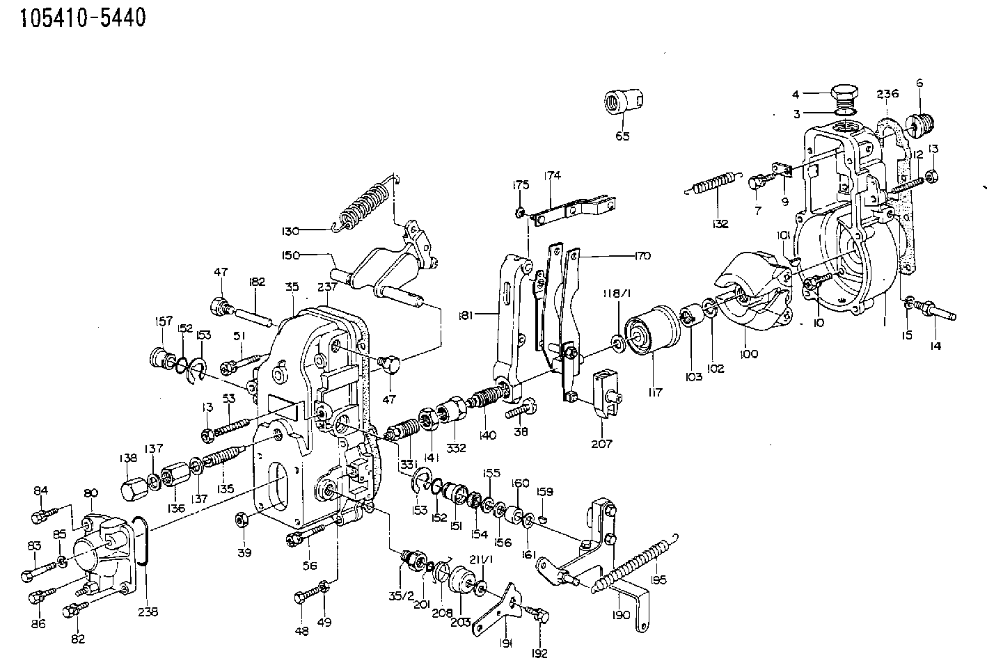
| 1. | [1] | 154000-6400 | GOVERNOR HOUSING |
| 3. | [1] | 029632-5070 | O-RING |
| 4. | [1] | 154007-2900 | CAPSULE |
| 6. | [1] | 154007-0200 | ADAPTOR |
| 7. | [1] | 020018-1840 | BLEEDER SCREW M8P1.25L18 |
| 9. | [1] | 154350-1900 | PLATE |
| 10. | [6] | 029010-6810 | BLEEDER SCREW |
| 12. | [1] | 154010-0100 | FLAT-HEAD SCREW |
| 13. | [2] | 154011-0100 | HEXAGON NUT |
| 13. | [2] | 154011-0100 | HEXAGON NUT |
| 14. | [1] | 154012-1500 | BLEEDER SCREW |
| 15. | [1] | 014110-8440 | LOCKING WASHER |
| 35. | [1] | 154500-3720 | GOVERNOR COVER |
| 35/2. | [1] | 154321-0400 | BUSHING |
| 38. | [1] | 154031-0100 | FLAT-HEAD SCREW |
| 39. | [1] | 013020-6020 | UNION NUT M6P1H5 |
| 47. | [2] | 154036-0300 | CAPSULE |
| 47. | [2] | 154036-0300 | CAPSULE |
| 48. | [1] | 154037-0700 | BLEEDER SCREW |
| 49. | [1] | 154038-0200 | HEXAGON NUT |
| 51. | [2] | 020106-5040 | BLEEDER SCREW |
| 53. | [1] | 154010-0200 | FLAT-HEAD SCREW |
| 56. | [4] | 020106-3840 | BLEEDER SCREW |
| 65. | [1] | 155404-0200 | CAP |
| 80. | [1] | 154063-1220 | COVER |
| 82. | [1] | 020006-1640 | BLEEDER SCREW M6P1L16 4T |
| 83. | [1] | 020006-1640 | BLEEDER SCREW M6P1L16 4T |
| 84. | [1] | 029020-6250 | BLEEDER SCREW |
| 85. | [1] | 014110-6440 | LOCKING WASHER |
| 86. | [1] | 020006-1640 | BLEEDER SCREW M6P1L16 4T |
| 100. | [0] | 154100-8520 | |
| 100. | [1] | 154101-0020 | FLYWEIGHT ASSEMBLY |
| 101. | [1] | 025803-1610 | WOODRUFF KEY |
| 102. | [1] | 029321-2020 | LOCKING WASHER |
| 103. | [1] | 029231-2030 | UNION NUT |
| 117. | [1] | 154123-0120 | SLIDING PIECE |
| 118/1. | [0] | 029311-0010 | SHIM D14&10.1T0.2 |
| 118/1. | [0] | 029311-0180 | SHIM D14&10.1T0.3 |
| 118/1. | [0] | 029311-0190 | SHIM D14&10.1T0.40 |
| 118/1. | [0] | 029311-0210 | SHIM D14&10.1T1 |
| 118/1. | [0] | 139410-0000 | SHIM D14.0&10.1T0.5 |
| 118/1. | [0] | 139410-0100 | SHIM D14.0&10.1T1.5 |
| 118/1. | [0] | 139410-3000 | SHIM D14&10.1T2.0 |
| 118/1. | [0] | 139410-3100 | SHIM D14&10.1T3.0 |
| 118/1. | [0] | 139410-3200 | SHIM D14&10.1T4.0 |
| 130. | [1] | 154150-2700 | GOVERNOR SPRING |
| 132. | [1] | 154154-0701 | COILED SPRING |
| 135. | [1] | 154158-0920 | HEADLESS SCREW |
| 136. | [1] | 154011-1700 | UNION NUT |
| 137. | [2] | 026512-1540 | GASKET D15.4&12.2T1.50 |
| 137. | [2] | 026512-1540 | GASKET D15.4&12.2T1.50 |
| 138. | [1] | 154159-1200 | CAP NUT |
| 140. | [1] | 154178-1820 | HEADLESS SCREW |
| 141. | [1] | 029201-6080 | UNION NUT |
| 150. | [1] | 154200-7220 | SWIVELLING LEVER |
| 151. | [1] | 154204-4300 | BUSHING |
| 152. | [2] | 029631-8020 | O-RING |
| 152. | [2] | 029631-8020 | O-RING |
| 153. | [2] | 016010-1640 | LOCKING WASHER |
| 153. | [2] | 016010-1640 | LOCKING WASHER |
| 154. | [1] | 139611-0000 | PACKING RING |
| 155. | [1] | 139411-0000 | SHIM |
| 156. | [0] | 029311-1070 | SHIM D16&11T0.5 |
| 157. | [1] | 154204-4400 | BUSHING |
| 159. | [1] | 025803-1310 | WOODRUFF KEY |
| 160. | [1] | 154206-2800 | BUSHING |
| 161. | [0] | 154206-0200 | PLAIN WASHER D19.5&11.2T1.0 |
| 170. | [1] | 154210-7420 | FORK LEVER |
| 174. | [1] | 154230-3920 | STRAP |
| 175. | [1] | 016010-0540 | LOCKING WASHER |
| 181. | [1] | 154236-1500 | TENSIONING LEVER |
| 182. | [1] | 154237-0100 | BEARING PIN |
| 190. | [1] | 154342-1420 | CONTROL LEVER |
| 191. | [1] | 154307-0100 | CONTROL LEVER |
| 192. | [1] | 020006-1640 | BLEEDER SCREW M6P1L16 4T |
| 195. | [1] | 154314-0200 | COILED SPRING |
| 201. | [1] | 029631-0030 | O-RING &9.8W2.3 |
| 203. | [1] | 154322-0100 | CAP |
| 207. | [1] | 154326-5120 | CONTROL LEVER |
| 208. | [1] | 154327-7300 | COILED SPRING |
| 211/1. | [0] | 029311-0520 | SHIM D20.8&10.3T0.2 |
| 211/1. | [0] | 029311-0530 | SHIM D20.8&10.3T0.25 |
| 211/1. | [0] | 029311-0540 | SHIM D20.8&10.3T0.3 |
| 211/1. | [0] | 029311-0550 | SHIM D20.8&10.3T0.35 |
| 211/1. | [0] | 029311-0560 | SHIM D20.8&10.3T0.4 |
| 211/1. | [0] | 029311-0570 | SHIM D20.8&10.3T0.5 |
| 236. | [1] | 154390-0000 | GASKET |
| 237. | [1] | 154390-0300 | GASKET |
| 238. | [1] | 029635-2020 | O-RING |
| 331. | [1] | 154172-2820 | HEADLESS SCREW |
| 332. | [1] | 029201-6010 | UNION NUT |
Include in #1:
101602-4120
as GOVERNOR
Cross reference number
Zexel num
Bosch num
Firm num
Name
105410-5440
1157204890 ISUZU
GOVERNOR
* K 14JB MECHANICAL GOVERNOR GOV RSV GOV
* K 14JB MECHANICAL GOVERNOR GOV RSV GOV
Information:
14. Put clean engine oil on the camshaft bearings and on camshaft (21). Install camshaft as shown. 15. Install camshaft gear (22) and retainer (23). Install the three bolts. 16. Put clean engine oil on lifters (25). Install lifters (25) and spacers (24) for each of the injection pumps. Be sure the lifters and spacers are put in their original location. 17. Put clean engine oil on the left and right fuel racks. Install left rack in the pump housing with the groove in the rack engaged with the tab of the rack bearing. Install right rack (26) with the groove in the rack engaged with the tab of the rack bearing. 18. Install dowel (27) in the pump housing until it is extended 12.2 0.5 mm (.48 .02 in) from the surface of the pump housing.19. Install link (29) and bracket assembly (30). Install bolt (28). Be careful so bracket (30) does not turn as bolt (28) is tightened. 20. Install Tool (E) in the injection pump housing to hold the racks in the center (zero) position.21. Put the space in gear segment (32) in alignment with the groove in pump barrel (31). Put the injection pump straight down into the housing bore with the space in gear segment (32) engaged with the pin in the lifter and the groove in barrel (31) engaged with the dowel in the pump housing. Use Tool (F) to install the pump. 22. Install seal (33) and bushing (34) in the pump housing bore. If the injection pump is in the correct position, bushing (34) will turn into the threads of the pump housing with the fingers until it is even with the housing.23. Tighten bushings (34) to a torque of 205 14 N m (150 10 lb ft) with Tool (G). 24. Install a felt washer (35) and protection caps for each injection pump. For more detail see the topic "Install Fuel Injection Pumps" in this module. 25. Heat gear (36) to a maximum temperature of 232°C (450°F) and install it on the shaft. 26. Install bearing in housing (37) with Tooling (C). 27. Install shaft and gear assembly (40) in fuel injection housing. Install gasket (39) on housing. Install small cover (38). Install housing (37) on fuel injection housing with the bolts that hold it. 28. Install fuel transfer pump (41) in housing (37) with the bolts that hold it. 29. If replacement of the dowels (43) in the governor plate is necessary, see illustration A42792P1 for correct installation dimensions. 30. Install bearing (42) for drive gear with Tooling (C) until it is 0.51 mm (.020 in) from the top surface of the governor plate. 31. Install drive gear (44), install ring (45) with Tool (H). 32. Install O-ring seals (47) on cylinder (46). 33. Install cylinder (46) in governor plate with the notch in the cylinder in alignment with the bolt hole in the governor plate. 34. Install O-ring seal (49) on sleeve (51).