Information governor
BOSCH
F 019 Z1E 074
f019z1e074
ZEXEL
105410-5430
1054105430
ISUZU
5157202691
5157202691
Rating:
Scheme ###:
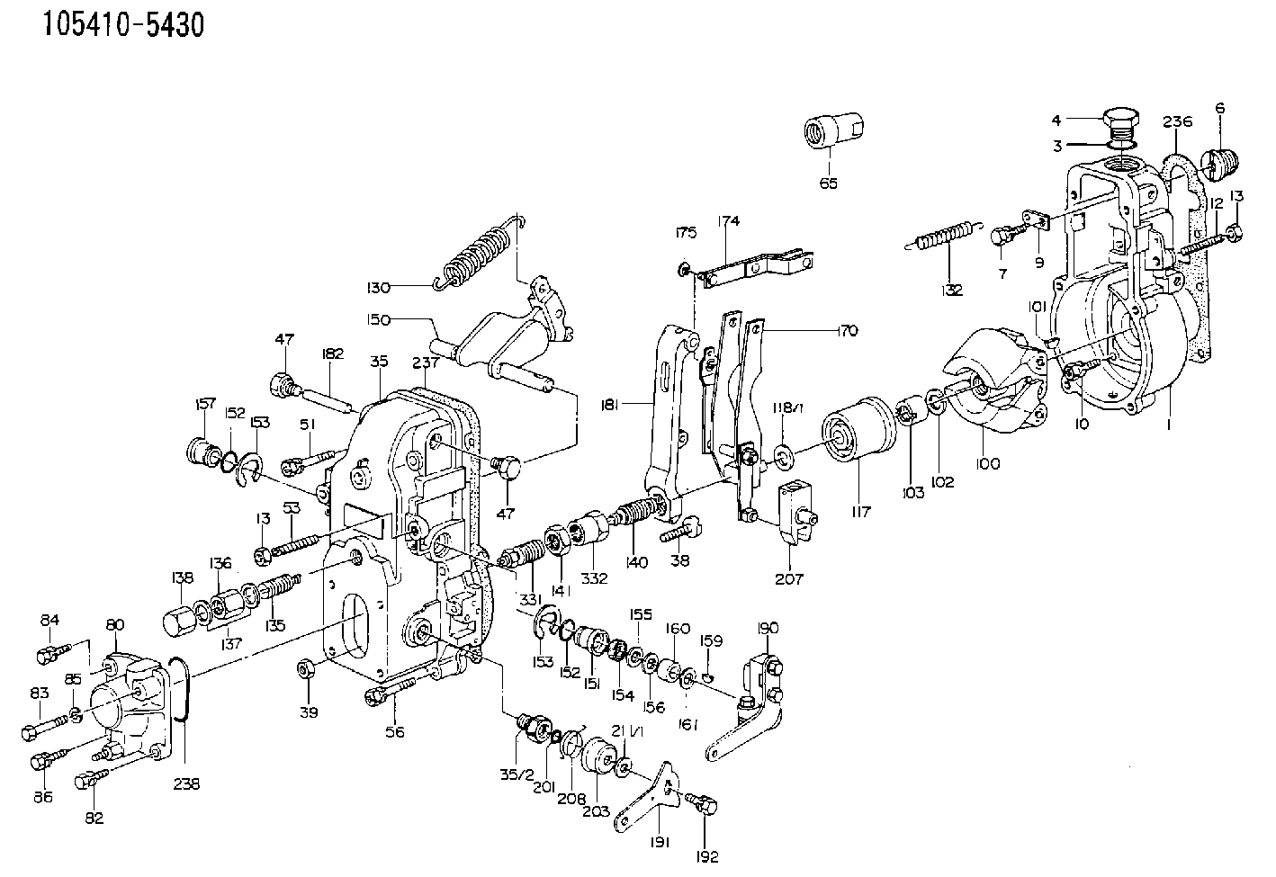
| 1. | [1] | 154000-6400 | GOVERNOR HOUSING |
| 3. | [1] | 029632-5070 | O-RING |
| 4. | [1] | 154007-2900 | CAPSULE |
| 6. | [1] | 154007-0200 | ADAPTOR |
| 7. | [1] | 020018-1840 | BLEEDER SCREW M8P1.25L18 |
| 9. | [1] | 154350-1900 | PLATE |
| 10. | [6] | 029010-6810 | BLEEDER SCREW |
| 12. | [1] | 154010-0100 | FLAT-HEAD SCREW |
| 13. | [2] | 154011-0100 | HEXAGON NUT |
| 13. | [2] | 154011-0100 | HEXAGON NUT |
| 35. | [1] | 154500-3020 | GOVERNOR COVER |
| 35/2. | [1] | 154321-0400 | BUSHING |
| 38. | [1] | 154031-0100 | FLAT-HEAD SCREW |
| 39. | [1] | 013020-6020 | UNION NUT M6P1H5 |
| 47. | [2] | 154036-0300 | CAPSULE |
| 47. | [2] | 154036-0300 | CAPSULE |
| 51. | [2] | 020106-5040 | BLEEDER SCREW |
| 53. | [1] | 154010-0200 | FLAT-HEAD SCREW |
| 56. | [4] | 020106-3840 | BLEEDER SCREW |
| 65. | [1] | 155404-0200 | CAP |
| 80. | [1] | 154063-1220 | COVER |
| 82. | [1] | 029020-6210 | BLEEDER SCREW |
| 83. | [1] | 029020-6210 | BLEEDER SCREW |
| 84. | [1] | 010006-3840 | BLEEDER SCREW |
| 85. | [1] | 014110-6440 | LOCKING WASHER |
| 86. | [1] | 020006-1640 | BLEEDER SCREW M6P1L16 4T |
| 100. | [1] | 154101-0020 | FLYWEIGHT ASSEMBLY |
| 101. | [1] | 025803-1610 | WOODRUFF KEY |
| 102. | [1] | 029321-2020 | LOCKING WASHER |
| 103. | [1] | 029231-2030 | UNION NUT |
| 117. | [1] | 154123-0120 | SLIDING PIECE |
| 118/1. | [0] | 029311-0010 | SHIM D14&10.1T0.2 |
| 118/1. | [0] | 029311-0180 | SHIM D14&10.1T0.3 |
| 118/1. | [0] | 029311-0190 | SHIM D14&10.1T0.40 |
| 118/1. | [0] | 029311-0210 | SHIM D14&10.1T1 |
| 118/1. | [0] | 139410-0000 | SHIM D14.0&10.1T0.5 |
| 118/1. | [0] | 139410-0100 | SHIM D14.0&10.1T1.5 |
| 118/1. | [0] | 139410-3000 | SHIM D14&10.1T2.0 |
| 118/1. | [0] | 139410-3100 | SHIM D14&10.1T3.0 |
| 118/1. | [0] | 139410-3200 | SHIM D14&10.1T4.0 |
| 130. | [1] | 154150-0400 | GOVERNOR SPRING |
| 132. | [1] | 154154-0500 | COILED SPRING |
| 135. | [1] | 154158-2320 | HEADLESS SCREW |
| 136. | [1] | 154011-1700 | UNION NUT |
| 137. | [2] | 026512-1540 | GASKET D15.4&12.2T1.50 |
| 138. | [1] | 154159-1200 | CAP NUT |
| 140. | [1] | 154185-3920 | HEADLESS SCREW |
| 141. | [1] | 029201-6080 | UNION NUT |
| 150. | [1] | 154200-6920 | SWIVELLING LEVER |
| 151. | [1] | 154204-4300 | BUSHING |
| 152. | [2] | 029631-8020 | O-RING |
| 152. | [2] | 029631-8020 | O-RING |
| 153. | [2] | 016010-1640 | LOCKING WASHER |
| 153. | [2] | 016010-1640 | LOCKING WASHER |
| 154. | [1] | 139611-0000 | PACKING RING |
| 155. | [1] | 139411-0000 | SHIM |
| 156. | [0] | 029311-1070 | SHIM D16&11T0.5 |
| 157. | [1] | 154204-4400 | BUSHING |
| 159. | [1] | 025803-1310 | WOODRUFF KEY |
| 160. | [1] | 154206-2800 | BUSHING |
| 161. | [0] | 154206-0200 | PLAIN WASHER D19.5&11.2T1.0 |
| 170. | [1] | 154210-7420 | FORK LEVER |
| 174. | [1] | 154230-3920 | STRAP |
| 175. | [1] | 016010-0540 | LOCKING WASHER |
| 181. | [1] | 154236-4100 | TENSIONING LEVER |
| 182. | [1] | 154237-0100 | BEARING PIN |
| 190. | [1] | 154342-2520 | CONTROL LEVER |
| 191. | [1] | 154307-4100 | CONTROL LEVER |
| 192. | [1] | 020006-1640 | BLEEDER SCREW M6P1L16 4T |
| 201. | [1] | 029631-0030 | O-RING &9.8W2.3 |
| 203. | [1] | 154322-0100 | CAP |
| 207. | [1] | 154326-5120 | CONTROL LEVER |
| 208. | [1] | 154327-7300 | COILED SPRING |
| 211/1. | [0] | 029311-0520 | SHIM D20.8&10.3T0.2 |
| 211/1. | [0] | 029311-0530 | SHIM D20.8&10.3T0.25 |
| 211/1. | [0] | 029311-0540 | SHIM D20.8&10.3T0.3 |
| 211/1. | [0] | 029311-0550 | SHIM D20.8&10.3T0.35 |
| 211/1. | [0] | 029311-0560 | SHIM D20.8&10.3T0.4 |
| 211/1. | [0] | 029311-0570 | SHIM D20.8&10.3T0.5 |
| 236. | [1] | 154390-0000 | GASKET |
| 237. | [1] | 154390-0300 | GASKET |
| 238. | [1] | 029635-2020 | O-RING |
| 331. | [1] | 154179-2820 | HEADLESS SCREW |
| 332. | [1] | 029201-6010 | UNION NUT |
Include in #1:
101492-0011
as GOVERNOR
Cross reference number
Zexel num
Bosch num
Firm num
Name
105410-5430
5157202691 ISUZU
GOVERNOR
* K 14JB MECHANICAL GOVERNOR GOV RSV GOV
* K 14JB MECHANICAL GOVERNOR GOV RSV GOV
Information:
1. Remove the plug from location (1). Install Tool (A) in the hole with the square end down. Move the governor control to the "ON" position until the rack stops against Tool (A). The racks are now in center (zero) position. 2. Disconnect lines (2) from the fuel injection pumps. Remove washers (3). Put caps on all fuel openings.3. Remove bushing (4) with Tool (B).
When injection pumps, spacers and lifters are removed from the injection pump housing, keep the parts of each pump together so they can be installed back in their original location.
4. Remove fuel injection pump with Tool (C).
Be careful when the injection pumps are disassembled. Do not cause damage to the surface on the plunger. The plunger and barrel for each pump are made as a set. Do not put the plunger of one pump in the barrel of another pump. If one part has wear install a complete new pump assembly. Be careful when the plunger is put into the bore of the barrel.
5. Disassemble the fuel injection pump. Remove ring (6). Make a separation of bonnet (5) from the plunger and barrel assembly (7).
Do not remove the gear from the plunger. The gear and plunger are assembled and adjusted at the factory.
6. Remove the plunger and gear segment, washer and spring from the barrel.7. Remove the ring, spring, collar and valve from the barrel. 8. Remove spacer (8) from the pump bore.Install Fuel Injection Pumps
Make sure the fuel racks are in the center (zero) position before the fuel injection pumps are installed. 1. Put plunger (10), washer (5) and spring (9) in position on barrel (4). Put check valve assembly (7), spring (3) and collar (8) in position in bonnet (6). Connect bonnet (6) and barrel (4) together with ring (2). Keep seal (1) with bonnet for use at installation. 2. Put spacer (13) into position in the pump housing bore. Make sure the correct spacer is with each pump.3. Put the space in gear segment (11) in alignment with the groove in barrel (4). 4. Put the injection pump straight down into the housing bore so the space in gear segment (11) is in alignment with pin (12) and the groove in barrel (4) is in alignment with dowel (14). Use Tool (C) to install the pump. 5. Install the seal and bushing (15) in the pump housing bore. If the pump is in the correct position, bushing (15) will turn into the threads of the pump housing with the fingers until it is even with the housing. Tighten bushing (15) to a torque of 205 14 Nm (150 10 lb ft) with Tool (B).6. Install washers (16).7. Connect the fuel lines to the injection pumps and tighten fuel line nuts to a torque of 40 7 Nm (30 5 lb ft) with Tool (D).8. Check for correct installation of the injection pumps with the engine stopped. See the topic "Installation of Injection Pump" in the Systems