Information governor
BOSCH
F 019 Z1E 073
f019z1e073
ZEXEL
105410-5410
1054105410
ISUZU
5157202831
5157202831
Rating:
Scheme ###:
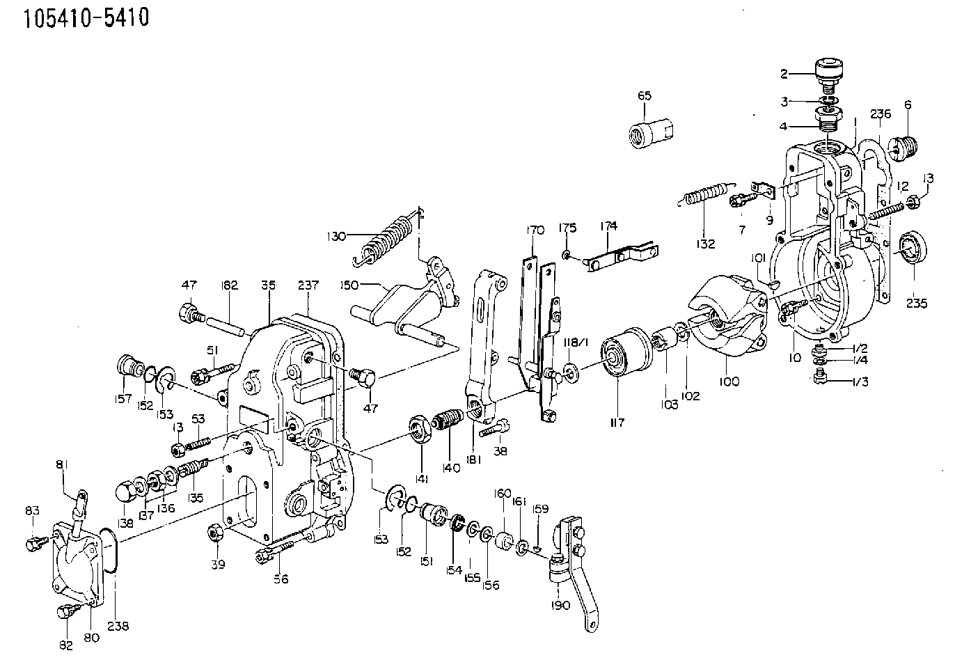
| 1. | [1] | 154000-3720 | GOVERNOR HOUSING |
| 1/2. | [1] | 155012-0700 | ADAPTOR |
| 1/3. | [1] | 029010-6010 | CAPSULE M6P1.0L7 |
| 1/4. | [1] | 026506-1040 | GASKET D9.9&6.2T1 |
| 2. | [1] | 155406-0120 | AIR FILTER |
| 3. | [1] | 026512-1540 | GASKET D15.4&12.2T1.50 |
| 4. | [1] | 154007-2600 | ADAPTOR |
| 6. | [1] | 154007-0200 | ADAPTOR |
| 7. | [1] | 020018-1840 | BLEEDER SCREW M8P1.25L18 |
| 9. | [1] | 154350-1900 | PLATE |
| 10. | [6] | 029010-6810 | BLEEDER SCREW |
| 12. | [1] | 154010-0100 | FLAT-HEAD SCREW |
| 13. | [2] | 154011-0100 | HEXAGON NUT |
| 13. | [2] | 154011-0100 | HEXAGON NUT |
| 35. | [1] | 154500-2020 | GOVERNOR COVER |
| 38. | [1] | 154031-0100 | FLAT-HEAD SCREW |
| 39. | [1] | 013020-6020 | UNION NUT M6P1H5 |
| 47. | [2] | 154036-0300 | CAPSULE |
| 47. | [2] | 154036-0300 | CAPSULE |
| 51. | [2] | 020106-5040 | BLEEDER SCREW |
| 53. | [1] | 154010-0300 | FLAT-HEAD SCREW |
| 56. | [4] | 020106-3840 | BLEEDER SCREW |
| 65. | [1] | 155404-0200 | CAP |
| 80. | [1] | 154060-6420 | COVER |
| 81. | [1] | 131029-4620 | LEVEL INDICATOR |
| 82. | [2] | 029020-6210 | BLEEDER SCREW |
| 83. | [2] | 020006-1640 | BLEEDER SCREW M6P1L16 4T |
| 100. | [1] | 154100-2320 | FLYWEIGHT ASSEMBLY |
| 101. | [1] | 025803-1610 | WOODRUFF KEY |
| 102. | [1] | 029321-2020 | LOCKING WASHER |
| 103. | [1] | 029231-2030 | UNION NUT |
| 117. | [1] | 154123-0120 | SLIDING PIECE |
| 118/1. | [0] | 029311-0010 | SHIM D14&10.1T0.2 |
| 118/1. | [0] | 029311-0180 | SHIM D14&10.1T0.3 |
| 118/1. | [0] | 029311-0190 | SHIM D14&10.1T0.40 |
| 118/1. | [0] | 029311-0210 | SHIM D14&10.1T1 |
| 118/1. | [0] | 139410-0000 | SHIM D14.0&10.1T0.5 |
| 118/1. | [0] | 139410-0100 | SHIM D14.0&10.1T1.5 |
| 118/1. | [0] | 139410-3000 | SHIM D14&10.1T2.0 |
| 118/1. | [0] | 139410-3100 | SHIM D14&10.1T3.0 |
| 118/1. | [0] | 139410-3200 | SHIM D14&10.1T4.0 |
| 130. | [1] | 154150-0400 | GOVERNOR SPRING |
| 132. | [1] | 154154-0701 | COILED SPRING |
| 135. | [1] | 154157-5220 | HEADLESS SCREW |
| 136. | [1] | 029201-2030 | UNION NUT M12P1.0H4 |
| 137. | [2] | 026512-1540 | GASKET D15.4&12.2T1.50 |
| 138. | [1] | 154159-1200 | CAP NUT |
| 140. | [1] | 154176-3020 | HEADLESS SCREW |
| 141. | [1] | 029201-6010 | UNION NUT |
| 150. | [1] | 154200-6920 | SWIVELLING LEVER |
| 151. | [1] | 154204-4300 | BUSHING |
| 152. | [2] | 029631-8020 | O-RING |
| 152. | [2] | 029631-8020 | O-RING |
| 153. | [2] | 016010-1640 | LOCKING WASHER |
| 153. | [2] | 016010-1640 | LOCKING WASHER |
| 154. | [1] | 139611-0000 | PACKING RING |
| 155. | [1] | 139411-0000 | SHIM |
| 156. | [0] | 029311-1070 | SHIM D16&11T0.5 |
| 157. | [1] | 154204-4400 | BUSHING |
| 159. | [1] | 025803-1310 | WOODRUFF KEY |
| 160. | [1] | 154206-2800 | BUSHING |
| 161. | [0] | 154206-0200 | PLAIN WASHER D19.5&11.2T1.0 |
| 170. | [1] | 154211-3820 | FORK LEVER |
| 174. | [1] | 154230-0120 | STRAP |
| 175. | [1] | 016010-0540 | LOCKING WASHER |
| 181. | [1] | 154236-4100 | TENSIONING LEVER |
| 182. | [1] | 154237-0100 | BEARING PIN |
| 190. | [1] | 154303-4120 | CONTROL LEVER |
| 235. | [1] | 029621-7010 | PACKING RING |
| 236. | [1] | 154390-0000 | GASKET |
| 237. | [1] | 154390-0300 | GASKET |
| 238. | [1] | 029635-2020 | O-RING |
Cross reference number
Zexel num
Bosch num
Firm num
Name
105410-5410
5157202831 ISUZU
GOVERNOR
K 14JB MECHANICAL GOVERNOR GOV RSV GOV
K 14JB MECHANICAL GOVERNOR GOV RSV GOV
105410-5410
65157202831 ISEKI
GOVERNOR
K 14JB MECHANICAL GOVERNOR GOV RSV GOV
K 14JB MECHANICAL GOVERNOR GOV RSV GOV
Information:
1. Disconnect air line (1) at fitting. Remove two bolts (2). Pull up and toward the front of the engine to remove the bolt of the fuel ratio from the groove (slot) in the collar for the governor. Remove fuel ratio control (3). Remove gasket from fuel ratio control.2. Install a new gasket on fuel ratio control. Install fuel ratio control (3). Make sure bolt engages with stop collar in governor control.3. Install two bolts (2). Connect air line (1) at fitting.4. Make sure the fuel ratio control is in correct adjustment. See Systems Operation Testing & Adjusting Manual for this procedure.5. Install a new governor seal.Disassemble Fuel Ratio Control
Start By:a. remove fuel ratio control 1. Remove two bolts (1) and the housing (2). 2. Remove valve assembly (3).3. Remove seal (4) and O-ring seal from valve.4. Remove the retainer (5) and two springs (6). 5. Remove three bolts (9) and cover (10).6. Remove valve (7), diaphragm (8), retainer and spring. 7. Remove pin (12) from valve (7).8. Remove cover (11) from the valve.9. Remove the seal from the cover (11).Assemble Fuel Ratio Control
1. Put clean engine oil on lip of seal. Install the seal (1) in cover (2). Install seal so lip of seal is toward the inside of the cover. 2. Install the valve (3) into cover (2).3. Install the pin that holds cover on valve. 4. Install spring (7) and the retainer (6) in cover (8).5. Install diaphragm (5) on the valve assembly (4) and in the cover. 6. Install cover and three bolts (11) that hold covers together.7. Put clean engine oil on seal and ring seal. Install the seals (10) on valve.8. Install the two springs (13), retainer and valve assembly (12).9. Install housing (9) and two bolts.
Correct adjustment must be made to fuel ratio control before installation. See Systems Operation Testing & Adjusting for this procedure.
End By:a. install fuel ratio control