Information governor
BOSCH
9 420 614 782
9420614782
ZEXEL
105410-5320
1054105320
ISUZU
1157203370
1157203370
Rating:
Scheme ###:
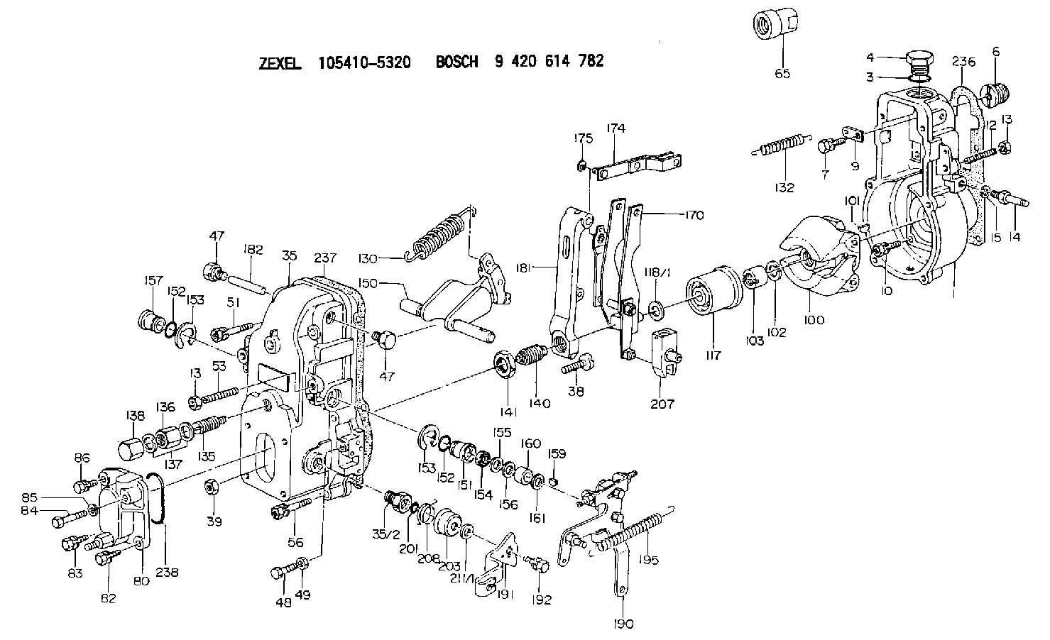
| 1. | [1] | 154000-6400 | GOVERNOR HOUSING |
| 3. | [1] | 029632-5070 | O-RING |
| 4. | [1] | 154007-2900 | CAPSULE |
| 6. | [1] | 154007-0200 | ADAPTOR |
| 7. | [1] | 020018-1840 | BLEEDER SCREW M8P1.25L18 |
| 9. | [1] | 154350-1900 | PLATE |
| 10. | [6] | 029010-6810 | BLEEDER SCREW |
| 12. | [1] | 154010-0100 | FLAT-HEAD SCREW |
| 13. | [2] | 154011-0100 | HEXAGON NUT |
| 13. | [2] | 154011-0100 | HEXAGON NUT |
| 14. | [1] | 154012-1500 | BLEEDER SCREW |
| 15. | [1] | 014110-8440 | LOCKING WASHER |
| 35. | [1] | 154500-3720 | GOVERNOR COVER |
| 35/2. | [1] | 154321-0400 | BUSHING |
| 38. | [1] | 154031-0100 | FLAT-HEAD SCREW |
| 39. | [1] | 013020-6020 | UNION NUT M6P1H5 |
| 47. | [2] | 154036-0300 | CAPSULE |
| 47. | [2] | 154036-0300 | CAPSULE |
| 48. | [1] | 154037-0700 | BLEEDER SCREW |
| 49. | [1] | 154038-0200 | HEXAGON NUT |
| 51. | [2] | 020106-5040 | BLEEDER SCREW |
| 53. | [1] | 154010-0200 | FLAT-HEAD SCREW |
| 56. | [4] | 020106-3840 | BLEEDER SCREW |
| 65. | [1] | 155404-0200 | CAP |
| 80. | [1] | 154060-1020 | COVER |
| 82. | [1] | 020006-1640 | BLEEDER SCREW M6P1L16 4T |
| 83. | [1] | 020006-1640 | BLEEDER SCREW M6P1L16 4T |
| 84. | [1] | 029020-6220 | BLEEDER SCREW |
| 85. | [1] | 014110-6440 | LOCKING WASHER |
| 86. | [1] | 020006-1640 | BLEEDER SCREW M6P1L16 4T |
| 100. | [1] | 154101-0020 | FLYWEIGHT ASSEMBLY |
| 101. | [1] | 025803-1610 | WOODRUFF KEY |
| 102. | [1] | 029321-2020 | LOCKING WASHER |
| 103. | [1] | 029231-2030 | UNION NUT |
| 117. | [1] | 154123-0120 | SLIDING PIECE |
| 118/1. | [0] | 029311-0010 | SHIM D14&10.1T0.2 |
| 118/1. | [0] | 029311-0180 | SHIM D14&10.1T0.3 |
| 118/1. | [0] | 029311-0190 | SHIM D14&10.1T0.40 |
| 118/1. | [0] | 029311-0210 | SHIM D14&10.1T1 |
| 118/1. | [0] | 139410-0000 | SHIM D14.0&10.1T0.5 |
| 118/1. | [0] | 139410-0100 | SHIM D14.0&10.1T1.5 |
| 118/1. | [0] | 139410-3000 | SHIM D14&10.1T2.0 |
| 118/1. | [0] | 139410-3100 | SHIM D14&10.1T3.0 |
| 118/1. | [0] | 139410-3200 | SHIM D14&10.1T4.0 |
| 130. | [1] | 154150-0200 | GOVERNOR SPRING |
| 132. | [1] | 154154-0800 | COILED SPRING |
| 135. | [1] | 154158-0920 | HEADLESS SCREW |
| 136. | [1] | 154011-2700 | UNION NUT |
| 137. | [2] | 026512-1540 | GASKET D15.4&12.2T1.50 |
| 138. | [1] | 154159-1200 | CAP NUT |
| 140. | [1] | 154178-9220 | HEADLESS SCREW |
| 141. | [1] | 029201-6010 | UNION NUT |
| 150. | [1] | 154200-6920 | SWIVELLING LEVER |
| 151. | [1] | 154204-4300 | BUSHING |
| 152. | [2] | 029631-8020 | O-RING |
| 152. | [2] | 029631-8020 | O-RING |
| 153. | [2] | 016010-1640 | LOCKING WASHER |
| 153. | [2] | 016010-1640 | LOCKING WASHER |
| 154. | [1] | 139611-0000 | PACKING RING |
| 155. | [1] | 139411-0000 | SHIM |
| 156. | [0] | 029311-1070 | SHIM D16&11T0.5 |
| 157. | [1] | 154204-4400 | BUSHING |
| 159. | [1] | 025803-1310 | WOODRUFF KEY |
| 160. | [1] | 154206-2800 | BUSHING |
| 161. | [0] | 154206-0200 | PLAIN WASHER D19.5&11.2T1.0 |
| 170. | [1] | 154210-7420 | FORK LEVER |
| 174. | [1] | 154230-3920 | STRAP |
| 175. | [1] | 016010-0540 | LOCKING WASHER |
| 181. | [1] | 154236-4100 | TENSIONING LEVER |
| 182. | [1] | 154237-0100 | BEARING PIN |
| 190. | [1] | 154342-3620 | CONTROL LEVER |
| 191. | [1] | 154304-8900 | CONTROL LEVER |
| 192. | [1] | 020006-1640 | BLEEDER SCREW M6P1L16 4T |
| 195. | [1] | 154314-0200 | COILED SPRING |
| 201. | [1] | 029631-0030 | O-RING &9.8W2.3 |
| 203. | [1] | 154322-0100 | CAP |
| 207. | [1] | 154326-5120 | CONTROL LEVER |
| 208. | [1] | 154327-7300 | COILED SPRING |
| 211/1. | [0] | 029311-0520 | SHIM D20.8&10.3T0.2 |
| 211/1. | [0] | 029311-0530 | SHIM D20.8&10.3T0.25 |
| 211/1. | [0] | 029311-0540 | SHIM D20.8&10.3T0.3 |
| 211/1. | [0] | 029311-0550 | SHIM D20.8&10.3T0.35 |
| 211/1. | [0] | 029311-0560 | SHIM D20.8&10.3T0.4 |
| 211/1. | [0] | 029311-0570 | SHIM D20.8&10.3T0.5 |
| 236. | [1] | 154390-0000 | GASKET |
| 237. | [1] | 154390-0300 | GASKET |
| 238. | [1] | 029635-2020 | O-RING |
Cross reference number
Zexel num
Bosch num
Firm num
Name
105410-5320
1157203370 ISUZU
GOVERNOR
K 14JB MECHANICAL GOVERNOR GOV RSV GOV
K 14JB MECHANICAL GOVERNOR GOV RSV GOV
105410-5320
1157205570 ISUZU
GOVERNOR
A K 14JB MECHANICAL GOVERNOR GOV RSV GOV
A K 14JB MECHANICAL GOVERNOR GOV RSV GOV
105410-5320
1157207000 ISUZU
GOVERNOR
B K 14JB MECHANICAL GOVERNOR GOV RSV GOV
B K 14JB MECHANICAL GOVERNOR GOV RSV GOV
105410-5320
1157207630 ISUZU
GOVERNOR
C K 14JB MECHANICAL GOVERNOR GOV RSV GOV
C K 14JB MECHANICAL GOVERNOR GOV RSV GOV
Information:
Start By:a. remove valve covers
Do not let the tops of the fuel injection nozzles turn when the fuel lines are loosened. The nozzles will be damaged if the top of the nozzles turn in the body.
1. Use Tooling (A) to loosen the nuts on the fuel injection line.2. Remove fuel injection lines (1).3. Disconnect fuel injection line nut (2) from head adapter nut (3).4. Remove adapter nut (3) and the O-ring seal. 5. Remove four bolts (4) that hold rocker arm assembly (5), and remove rocker arm assembly (5).Install Rocker Shaft Assemblies
1. Check the adjustment of the valve bridges. See the topic "Install Push Rods, Valve Lifters & Valve Bridges" in this module. 2. Loosen all the rocker arm adjusting screws on rocker shaft assembly (5).3. Install rocker shaft assembly (5).4. Clean the bolts that hold the rocker shaft assembly. Put 2P-2506 Thread Lubricant on the bolt threads, and install them.5. Be sure the rocker arms and push rods are in alignment before the rocker shaft assembly bolts are tightened.6. Tighten the rocker shaft bolts in the following sequence.a. Tighten bolts (1) through (4) in numerical sequence to a torque of 280 27 N m (210 20 lb ft).b. Tighten bolts (1) through (4) in numerical sequence to a torque of 440 20 N m (320 15 lb ft).c. Tighten bolts (1) through (4) in numerical sequence again to a final torque of 440 20 N m (320 15 lb ft). 7. Install a new O-ring seal on head adapter (7), and put clean engine oil on it.8. Put fuel injection line (8) in position, but do not tighten the nuts.9. Install adapters (7), and connect fuel injection lines (8).10. Connect fuel injection lines (6) to adapters (7).
Do not let the tops of the fuel injection nozzles turn when the fuel lines are tightened. The nozzles will be damaged if the top of the nozzles turn in the body.
11. Use Tooling (A) to tighten the fuel injection line nuts to a torque of 41 7 N m (30 5 lb ft).12. Adjust the valve clearance settings. The clearance for the intake valve is 0.38 mm (.015 in). The clearance for the exhaust valves is 0.76 mm (.030 in). See the topic "Valve Clearance Setting" in Testing & Adjusting.End By:a. install valve coversDisassemble Rocker Shaft Assemblies
Start By:a. remove rocker shaft assemblies 1. Remove retainer (1) from the end of the shaft.2. Remove the washers and rocker arm (2). 3. Use Tool (A) to remove the pin that holds bracket (3) to the rocker arm shaft.4. Remove bracket (3), rocker arm (4) and the spring.5. Remove the remainder of the rocker arms. The center brackets do not have pins.Assemble Rocker Shaft Assemblies
Make sure all parts of the rocker shaft assembly are clean before assembly. 1. Put clean engine oil on shaft (3).2. Install the center springs, rocker arms and bracket.3. Install spring (1), rocker arm (4) and bracket (2).4. Put tape