Information governor
BOSCH
F 019 Z1E 067
f019z1e067
ZEXEL
105410-5130
1054105130
ISUZU
1157203480
1157203480
Rating:
Scheme ###:
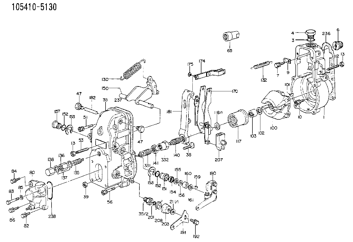
| 1. | [1] | 154000-6400 | GOVERNOR HOUSING |
| 3. | [1] | 029632-5070 | O-RING |
| 4. | [1] | 154007-2900 | CAPSULE |
| 6. | [1] | 154007-0200 | ADAPTOR |
| 7. | [1] | 020018-1840 | BLEEDER SCREW M8P1.25L18 |
| 9. | [1] | 154350-1900 | PLATE |
| 10. | [6] | 029010-6810 | BLEEDER SCREW |
| 12. | [1] | 154010-0100 | FLAT-HEAD SCREW |
| 13. | [2] | 154011-0100 | HEXAGON NUT |
| 13. | [2] | 154011-0100 | HEXAGON NUT |
| 14. | [1] | 154012-1500 | BLEEDER SCREW |
| 15. | [1] | 014110-8440 | LOCKING WASHER |
| 35. | [1] | 154500-3720 | GOVERNOR COVER |
| 35/2. | [1] | 154321-0400 | BUSHING |
| 38. | [1] | 154031-0100 | FLAT-HEAD SCREW |
| 39. | [1] | 013020-6020 | UNION NUT M6P1H5 |
| 47. | [2] | 154036-0300 | CAPSULE |
| 47. | [2] | 154036-0300 | CAPSULE |
| 48. | [1] | 154037-0700 | BLEEDER SCREW |
| 49. | [1] | 154038-0200 | HEXAGON NUT |
| 51. | [2] | 020106-5040 | BLEEDER SCREW |
| 53. | [1] | 154010-0200 | FLAT-HEAD SCREW |
| 56. | [4] | 020106-3840 | BLEEDER SCREW |
| 65. | [1] | 155404-0200 | CAP |
| 80. | [1] | 154063-0600 | COVER |
| 82. | [1] | 020006-1640 | BLEEDER SCREW M6P1L16 4T |
| 83. | [1] | 020006-1640 | BLEEDER SCREW M6P1L16 4T |
| 84. | [1] | 029020-6250 | BLEEDER SCREW |
| 85. | [1] | 014110-6440 | LOCKING WASHER |
| 86. | [1] | 020006-1640 | BLEEDER SCREW M6P1L16 4T |
| 100. | [1] | 154101-0020 | FLYWEIGHT ASSEMBLY |
| 101. | [1] | 025803-1610 | WOODRUFF KEY |
| 102. | [1] | 029321-2020 | LOCKING WASHER |
| 103. | [1] | 029231-2030 | UNION NUT |
| 117. | [1] | 154123-0120 | SLIDING PIECE |
| 118/1. | [0] | 029311-0010 | SHIM D14&10.1T0.2 |
| 118/1. | [0] | 029311-0180 | SHIM D14&10.1T0.3 |
| 118/1. | [0] | 029311-0190 | SHIM D14&10.1T0.40 |
| 118/1. | [0] | 029311-0210 | SHIM D14&10.1T1 |
| 118/1. | [0] | 139410-0000 | SHIM D14.0&10.1T0.5 |
| 118/1. | [0] | 139410-0100 | SHIM D14.0&10.1T1.5 |
| 118/1. | [0] | 139410-3000 | SHIM D14&10.1T2.0 |
| 118/1. | [0] | 139410-3100 | SHIM D14&10.1T3.0 |
| 118/1. | [0] | 139410-3200 | SHIM D14&10.1T4.0 |
| 130. | [1] | 154150-2900 | GOVERNOR SPRING |
| 132. | [1] | 154154-0800 | COILED SPRING |
| 135. | [1] | 154158-0920 | HEADLESS SCREW |
| 136. | [1] | 154011-1700 | UNION NUT |
| 137. | [2] | 026512-1540 | GASKET D15.4&12.2T1.50 |
| 138. | [1] | 154159-1200 | CAP NUT |
| 140. | [1] | 154178-1820 | HEADLESS SCREW |
| 141. | [1] | 029201-6080 | UNION NUT |
| 150. | [1] | 154200-6920 | SWIVELLING LEVER |
| 151. | [1] | 154204-4300 | BUSHING |
| 152. | [2] | 029631-8020 | O-RING |
| 152. | [2] | 029631-8020 | O-RING |
| 153. | [2] | 016010-1640 | LOCKING WASHER |
| 153. | [2] | 016010-1640 | LOCKING WASHER |
| 154. | [1] | 139611-0000 | PACKING RING |
| 155. | [1] | 139411-0000 | SHIM |
| 156. | [0] | 029311-1070 | SHIM D16&11T0.5 |
| 157. | [1] | 154204-4400 | BUSHING |
| 159. | [1] | 025803-1310 | WOODRUFF KEY |
| 160. | [1] | 154206-2800 | BUSHING |
| 161. | [0] | 154206-0200 | PLAIN WASHER D19.5&11.2T1.0 |
| 170. | [1] | 154210-7420 | FORK LEVER |
| 174. | [1] | 154230-3920 | STRAP |
| 175. | [1] | 016010-0540 | LOCKING WASHER |
| 181. | [1] | 154236-4100 | TENSIONING LEVER |
| 182. | [1] | 154237-0100 | BEARING PIN |
| 190. | [1] | 154342-1420 | CONTROL LEVER |
| 191. | [1] | 154307-0100 | CONTROL LEVER |
| 192. | [1] | 020006-1640 | BLEEDER SCREW M6P1L16 4T |
| 195. | [1] | 154314-0200 | COILED SPRING |
| 201. | [1] | 029631-0030 | O-RING &9.8W2.3 |
| 203. | [1] | 154322-0100 | CAP |
| 207. | [1] | 154326-5120 | CONTROL LEVER |
| 208. | [1] | 154327-7300 | COILED SPRING |
| 211/1. | [0] | 029311-0520 | SHIM D20.8&10.3T0.2 |
| 211/1. | [0] | 029311-0530 | SHIM D20.8&10.3T0.25 |
| 211/1. | [0] | 029311-0540 | SHIM D20.8&10.3T0.3 |
| 211/1. | [0] | 029311-0550 | SHIM D20.8&10.3T0.35 |
| 211/1. | [0] | 029311-0560 | SHIM D20.8&10.3T0.4 |
| 211/1. | [0] | 029311-0570 | SHIM D20.8&10.3T0.5 |
| 236. | [1] | 154390-0000 | GASKET |
| 237. | [1] | 154390-0300 | GASKET |
| 238. | [1] | 029635-2020 | O-RING |
| 331. | [1] | 154172-3920 | HEADLESS SCREW |
| 332. | [1] | 029201-6010 | UNION NUT |
Include in #1:
101602-0560
as GOVERNOR
Cross reference number
Zexel num
Bosch num
Firm num
Name
Information:
2. Loosen clamp (1).3. Remove two bolts (2).4. Remove two bolts (3) and washers.5. Remove water pump (4) and the gasket. When installing replace the gasket. Make sure all gasket surfaces are clean and free of dirt. For installation of the water pump, reverse the removal steps.6. Fill the radiator with coolant to the proper level. See the Operation & Maintenance Manual.Disassemble & Assemble Water Pump
The following tools are needed for disassembly. Start By:a. remove water pump 1. Remove bolt (15) and the washer. Remove bearing (12) and gear (10) as a unit.2. Use Tool (A), (C) and a press, and remove bearing (12) from gear (10).3. Remove snap ring (8) with Tool (B).4. Remove two bolts (1), the washers, cover (14) and gasket (2) from water pump housing (18).5. Loosen bolt (13) approximately 6.4 mm (.25 in). Hit the bolt with a soft hammer to loosen impeller (16) from shaft (9).6. Remove bolt (13), washer (11), impeller (16), spring (3) and seal assembly (4) from shaft (9).7. Remove bearing (7) and shaft (9) as a unit.8. Use Tool (A), (C) and a press to remove bearing (7) from shaft (9).9. Remove ceramic seal (5) and seal (17) from water pump housing (18).10. Use Tool (C) to remove lip-type seal (6) from the water pump housing. The following steps are for assembly of the water pump. The following tools are needed for assembly. 11. Install lip-type seal (6) in water pump housing (18) with Tool (C). The lip of the seal must be toward the bearings. Put clean engine oil on the lip of the seal.12. Install shaft (9) in bearing (7) with a press.13. Install shaft (9) and bearing (7) as a unit in water pump housing (18).14. Install snap ring (8) with Tool (B).
Clean water only is permitted for use as a lubricant for assembly. Do not damage or put hands on the wear surface of the carbon ring or the ceramic ring. Install the ceramic ring with the smoothest face of the ring toward the carbon seal assembly.
15. Put ceramic ring (5) in position in seal (17). Use hand pressure and Tool (D) to install the ceramic ring.16. Remove spring (3) from seal assembly (4). Use hand pressure and Tool (D) to install the seal assembly. Push seal assembly (4) on shaft (9) until it makes light contact with ceramic ring (5).17. Install spring (3) on seal assembly (4). Put impeller (16) in position on shaft (9), and install washer (11) and bolt (13) that hold it. Tighten bolt (13) to a torque of 38.0 1.5 N m (28 1 lb ft).18. Put gasket (2) and cover (14) in position on water pump housing (18). Install the two washers and bolts (1) that hold them.19. Install bearing (12) on gear (10) with a press.20. Position gear (10) and bearing (12) as a unit on shaft (9). Install the washer and bolt (15) that hold them together. Tighten bolt (15) to a torque of