Information governor
BOSCH
9 420 611 111
9420611111
ZEXEL
105410-5080
1054105080
ISUZU
1157204230
1157204230

Rating:
Scheme ###:
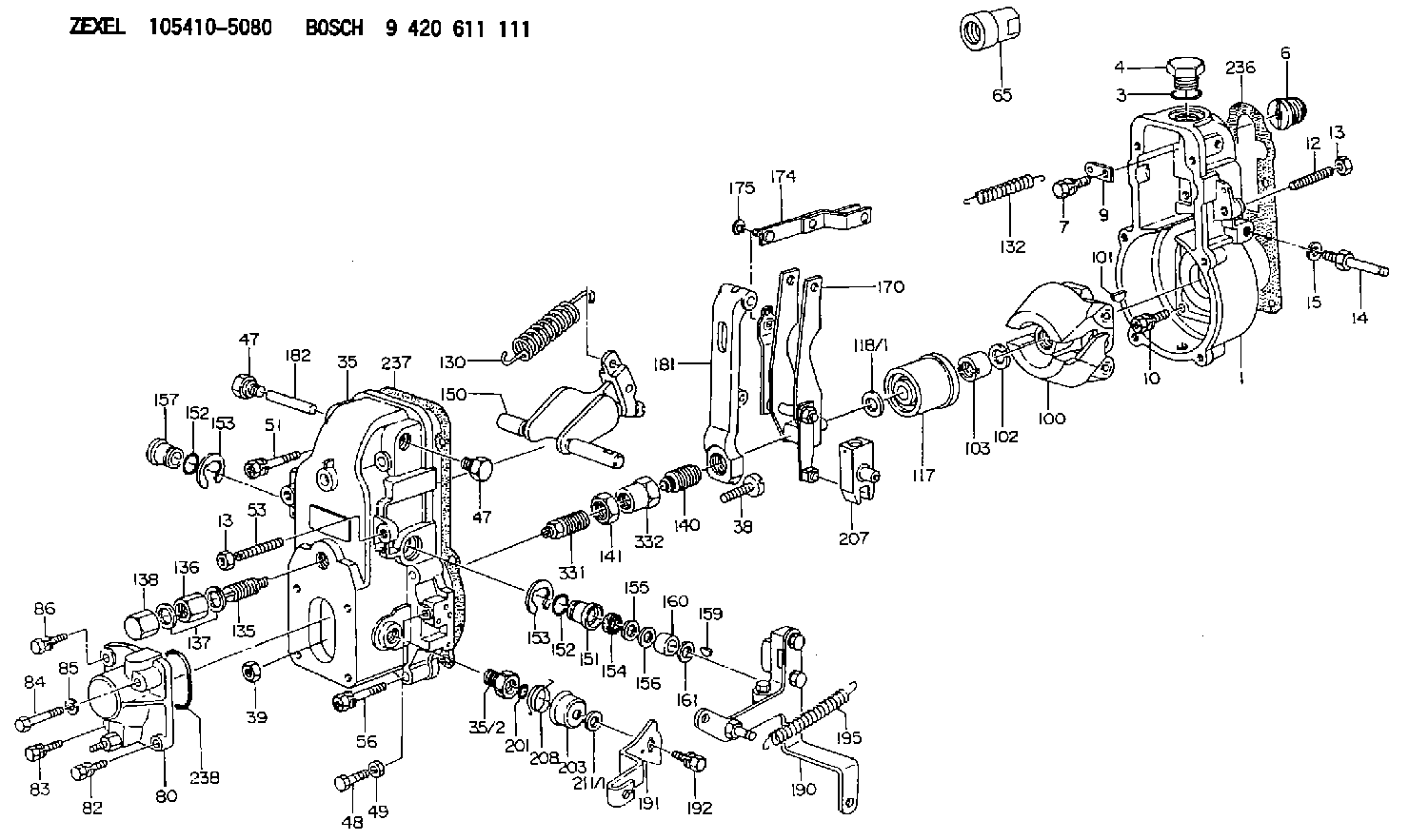
| 1. | [1] | 154000-6400 | GOVERNOR HOUSING |
| 3. | [1] | 029632-5070 | O-RING |
| 4. | [1] | 154007-2900 | CAPSULE |
| 6. | [1] | 154007-0200 | ADAPTOR |
| 7. | [1] | 020018-1840 | BLEEDER SCREW M8P1.25L18 |
| 9. | [1] | 154350-1900 | PLATE |
| 10. | [6] | 029010-6810 | BLEEDER SCREW |
| 12. | [1] | 154010-0100 | FLAT-HEAD SCREW |
| 13. | [2] | 154011-0100 | HEXAGON NUT |
| 13. | [2] | 154011-0100 | HEXAGON NUT |
| 14. | [1] | 154012-1500 | BLEEDER SCREW |
| 15. | [1] | 014110-8440 | LOCKING WASHER |
| 35. | [1] | 154500-3720 | GOVERNOR COVER |
| 35/2. | [1] | 154321-0400 | BUSHING |
| 38. | [1] | 154031-0100 | FLAT-HEAD SCREW |
| 39. | [1] | 013020-6020 | UNION NUT M6P1H5 |
| 47. | [2] | 154036-0300 | CAPSULE |
| 47. | [2] | 154036-0300 | CAPSULE |
| 48. | [1] | 154037-0700 | BLEEDER SCREW |
| 49. | [1] | 154038-0200 | HEXAGON NUT |
| 51. | [2] | 020106-5040 | BLEEDER SCREW |
| 53. | [1] | 154010-0200 | FLAT-HEAD SCREW |
| 56. | [4] | 020106-3840 | BLEEDER SCREW |
| 65. | [1] | 155404-0200 | CAP |
| 80. | [1] | 154063-1220 | COVER |
| 82. | [1] | 020006-1640 | BLEEDER SCREW M6P1L16 4T |
| 83. | [1] | 020006-1640 | BLEEDER SCREW M6P1L16 4T |
| 84. | [1] | 029020-6250 | BLEEDER SCREW |
| 85. | [1] | 014110-6440 | LOCKING WASHER |
| 86. | [1] | 020006-1640 | BLEEDER SCREW M6P1L16 4T |
| 100. | [1] | 154101-0020 | FLYWEIGHT ASSEMBLY |
| 101. | [1] | 025803-1610 | WOODRUFF KEY |
| 102. | [1] | 029321-2020 | LOCKING WASHER |
| 103. | [1] | 029231-2030 | UNION NUT |
| 117. | [1] | 154123-0120 | SLIDING PIECE |
| 118/1. | [0] | 029311-0010 | SHIM D14&10.1T0.2 |
| 118/1. | [0] | 029311-0180 | SHIM D14&10.1T0.3 |
| 118/1. | [0] | 029311-0190 | SHIM D14&10.1T0.40 |
| 118/1. | [0] | 029311-0210 | SHIM D14&10.1T1 |
| 118/1. | [0] | 139410-0000 | SHIM D14.0&10.1T0.5 |
| 118/1. | [0] | 139410-0100 | SHIM D14.0&10.1T1.5 |
| 118/1. | [0] | 139410-3000 | SHIM D14&10.1T2.0 |
| 118/1. | [0] | 139410-3100 | SHIM D14&10.1T3.0 |
| 118/1. | [0] | 139410-3200 | SHIM D14&10.1T4.0 |
| 130. | [1] | 154150-7700 | GOVERNOR SPRING |
| 132. | [1] | 154154-0701 | COILED SPRING |
| 135. | [1] | 154158-0920 | HEADLESS SCREW |
| 136. | [1] | 154011-1700 | UNION NUT |
| 137. | [2] | 026512-1540 | GASKET D15.4&12.2T1.50 |
| 138. | [1] | 154159-1200 | CAP NUT |
| 140. | [1] | 154185-2120 | HEADLESS SCREW |
| 141. | [1] | 029201-6080 | UNION NUT |
| 150. | [1] | 154200-7220 | SWIVELLING LEVER |
| 151. | [1] | 154204-3000 | BUSHING |
| 152. | [2] | 029631-8020 | O-RING |
| 152. | [2] | 029631-8020 | O-RING |
| 153. | [2] | 016010-1640 | LOCKING WASHER |
| 153. | [2] | 016010-1640 | LOCKING WASHER |
| 154. | [1] | 139611-0000 | PACKING RING |
| 155. | [1] | 139411-0000 | SHIM |
| 156. | [0] | 029311-1070 | SHIM D16&11T0.5 |
| 157. | [1] | 154204-3100 | BUSHING |
| 159. | [1] | 025803-1310 | WOODRUFF KEY |
| 160. | [1] | 154206-2800 | BUSHING |
| 161. | [0] | 154206-0200 | PLAIN WASHER D19.5&11.2T1.0 |
| 170. | [1] | 154210-7420 | FORK LEVER |
| 174. | [1] | 154230-3920 | STRAP |
| 175. | [1] | 016010-0540 | LOCKING WASHER |
| 181. | [1] | 154236-1500 | TENSIONING LEVER |
| 182. | [1] | 154237-0100 | BEARING PIN |
| 190. | [1] | 154342-1420 | CONTROL LEVER |
| 191. | [1] | 154304-8900 | CONTROL LEVER |
| 192. | [1] | 020006-1640 | BLEEDER SCREW M6P1L16 4T |
| 195. | [1] | 154314-0200 | COILED SPRING |
| 201. | [1] | 029631-0030 | O-RING &9.8W2.3 |
| 203. | [1] | 154322-0100 | CAP |
| 207. | [1] | 154326-5120 | CONTROL LEVER |
| 208. | [1] | 154327-7300 | COILED SPRING |
| 211/1. | [0] | 029311-0520 | SHIM D20.8&10.3T0.2 |
| 211/1. | [0] | 029311-0530 | SHIM D20.8&10.3T0.25 |
| 211/1. | [0] | 029311-0540 | SHIM D20.8&10.3T0.3 |
| 211/1. | [0] | 029311-0550 | SHIM D20.8&10.3T0.35 |
| 211/1. | [0] | 029311-0560 | SHIM D20.8&10.3T0.4 |
| 211/1. | [0] | 029311-0570 | SHIM D20.8&10.3T0.5 |
| 236. | [1] | 154390-0000 | GASKET |
| 237. | [1] | 154390-0300 | GASKET |
| 238. | [1] | 029635-2020 | O-RING |
| 331. | [1] | 154172-9320 | HEADLESS SCREW |
| 332. | [1] | 029201-6010 | UNION NUT |
Cross reference number
Zexel num
Bosch num
Firm num
Name
105410-5080
1157204230 ISUZU
GOVERNOR
K 14JB MECHANICAL GOVERNOR GOV RSV GOV
K 14JB MECHANICAL GOVERNOR GOV RSV GOV
105410-5080
1157700270 ISUZU
GOVERNOR
A K 14JB MECHANICAL GOVERNOR GOV RSV GOV
A K 14JB MECHANICAL GOVERNOR GOV RSV GOV
Information:
Start By:a. remove timing gear cover1. Time the engine as follows:a. Install Tool (A) in the flywheel housing.b. Remove the cover from the side of the fuel injection pump housing so the timing pin can be installed. Remove the plug from the flywheel housing so the timing bolt can be installed.c. Turn the engine in the direction of engine rotation until Tool (B) can be installed in fuel injection pump housing and located in the groove in the fuel injection pump camshaft, a 3/8" - 16 NC bolt can be installed in the flywheel through the hole in the flywheel housing, and the "C" marks on the crankshaft gear and the camshaft gear are in alignment with each other. 2. Loosen bolt (1) until there is approximately 3.18 mm (.125 in) gap between washer (2) and fuel pump drive gear (3).3. Install Tool (C) as shown, and loosen the fuel pump drive gear from the taper on the fuel injection pump camshaft. Remove Tool (C), the bolt, washer and fuel pump drive gear.4. Remove the bolts and plate (4) that hold idler gear (5) in position. Remove the idler gear. If necessary, remove the bearing from the idler gear with Tool (D) and a press.
Do not turn the crankshaft after camshaft gear (6) has been removed. Turning the crankshaft will cause damage to the valves.
5. Remove the four bolts that hold camshaft gear (6) to the camshaft. Remove the camshaft gear.Install Timing Gears
1. Make an alignment of the "C" marks on crankshaft gear (3) and camshaft gear (4). Install the camshaft gear and the bolts that hold it. Tighten the bolts to a torque of 55 7 N m (41 5 lb ft).2. Install the bearing in idler gear (1) with Tool (A). The end of the bearing must be 1.52 mm (.060 in) below the face of the gear hub after installation.3. Be sure the oil hole in the shaft for idler gear (1) is open. Put idler gear (1) and plate (2) in position on the shaft. Install the bolts that hold them. 4. Make sure Tool (C) is in position in the groove of the fuel injection pump camshaft.5. Put fuel injection pump drive gear (5) in position on the fuel injection pump camshaft. Put washer (6) in position on the gear with the largest diameter toward the front of the engine. Install bolt (7), and tighten it to a torque of 7 N m (5 lb ft). Make sure bolt (7) does not turn while the flywheel is being turned.6. Remove the timing bolt from the flywheel, and use Tool (B) to turn the flywheel in the opposite direction of engine rotation. Turn the flywheel until the "C" mark on the crankshaft gear moves 30°.7. Turn the flywheel in the direction of engine rotation until the timing bolt can be installed in the flywheel and the "C" marks are in alignment. This will remove all of the backlash from the timing gears.8.