Information governor
BOSCH
F 019 Z1E 593
f019z1e593
ZEXEL
105410-5070
1054105070
NISSAN-DIESEL
1910990070
1910990070

Rating:
Scheme ###:
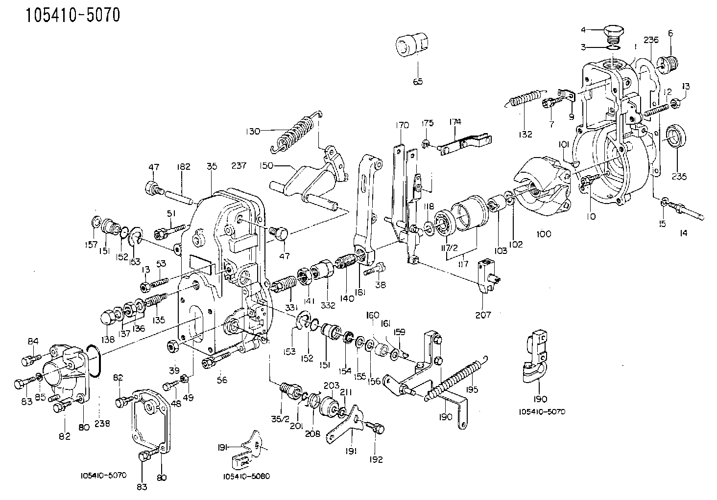
| 1. | [1] | 154000-6400 | GOVERNOR HOUSING |
| 3. | [1] | 029632-5070 | O-RING |
| 4. | [1] | 154007-2900 | CAPSULE |
| 6. | [1] | 154007-0200 | ADAPTOR |
| 7. | [1] | 020018-1840 | BLEEDER SCREW M8P1.25L18 |
| 9. | [1] | 154350-1900 | PLATE |
| 10. | [6] | 029010-6810 | BLEEDER SCREW |
| 12. | [1] | 154010-0100 | FLAT-HEAD SCREW |
| 13. | [2] | 154011-0100 | HEXAGON NUT |
| 13. | [2] | 154011-0100 | HEXAGON NUT |
| 35. | [1] | 154500-3020 | GOVERNOR COVER |
| 35/2. | [1] | 154321-0400 | BUSHING |
| 38. | [1] | 154031-0100 | FLAT-HEAD SCREW |
| 39. | [1] | 013020-6020 | UNION NUT M6P1H5 |
| 47. | [1] | 154036-0300 | CAPSULE |
| 47. | [1] | 154036-0300 | CAPSULE |
| 51. | [2] | 020106-5040 | BLEEDER SCREW |
| 53. | [1] | 154010-0100 | FLAT-HEAD SCREW |
| 56. | [4] | 020106-3840 | BLEEDER SCREW |
| 65. | [1] | 155404-3700 | CAP |
| 80. | [1] | 154060-4900 | COVER |
| 80. | [1] | 154060-4900 | COVER |
| 82. | [2] | 029020-6210 | BLEEDER SCREW |
| 82. | [2] | 029020-6210 | BLEEDER SCREW |
| 83. | [2] | 020006-1640 | BLEEDER SCREW M6P1L16 4T |
| 83. | [2] | 020006-1640 | BLEEDER SCREW M6P1L16 4T |
| 100. | [1] | 154100-4520 | FLYWEIGHT ASSEMBLY |
| 101. | [1] | 025803-1610 | WOODRUFF KEY |
| 102. | [1] | 029321-2020 | LOCKING WASHER |
| 103. | [1] | 029231-2030 | UNION NUT |
| 117. | [1] | 154123-0120 | SLIDING PIECE |
| 118/1. | [0] | 029311-0010 | SHIM D14&10.1T0.2 |
| 118/1. | [0] | 029311-0180 | SHIM D14&10.1T0.3 |
| 118/1. | [0] | 029311-0190 | SHIM D14&10.1T0.40 |
| 118/1. | [0] | 029311-0210 | SHIM D14&10.1T1 |
| 118/1. | [0] | 139410-0000 | SHIM D14.0&10.1T0.5 |
| 118/1. | [0] | 139410-0100 | SHIM D14.0&10.1T1.5 |
| 118/1. | [0] | 139410-3000 | SHIM D14&10.1T2.0 |
| 118/1. | [0] | 139410-3100 | SHIM D14&10.1T3.0 |
| 118/1. | [0] | 139410-3200 | SHIM D14&10.1T4.0 |
| 130. | [1] | 154150-0400 | GOVERNOR SPRING |
| 132. | [1] | 154154-0800 | COILED SPRING |
| 135. | [1] | 154157-0120 | HEADLESS SCREW |
| 136. | [1] | 029201-2030 | UNION NUT M12P1.0H4 |
| 137. | [2] | 026512-1540 | GASKET D15.4&12.2T1.50 |
| 138. | [1] | 154159-0100 | CAP NUT |
| 140. | [1] | 154185-0220 | HEADLESS SCREW |
| 141. | [1] | 029201-6010 | UNION NUT |
| 150. | [1] | 154200-6920 | SWIVELLING LEVER |
| 151. | [1] | 154204-4300 | BUSHING |
| 151. | [1] | 154204-4300 | BUSHING |
| 152. | [2] | 029631-8020 | O-RING |
| 152. | [2] | 029631-8020 | O-RING |
| 153. | [2] | 016010-1640 | LOCKING WASHER |
| 153. | [2] | 016010-1640 | LOCKING WASHER |
| 154. | [1] | 139611-0000 | PACKING RING |
| 155. | [1] | 139411-0000 | SHIM |
| 156. | [0] | 029311-1070 | SHIM D16&11T0.5 |
| 157. | [1] | 154204-4400 | BUSHING |
| 159. | [1] | 025803-1310 | WOODRUFF KEY |
| 160. | [1] | 154206-2800 | BUSHING |
| 161. | [0] | 154206-0200 | PLAIN WASHER D19.5&11.2T1.0 |
| 170. | [1] | 154210-0820 | FORK LEVER |
| 174. | [1] | 154230-3920 | STRAP |
| 175. | [1] | 016010-0540 | LOCKING WASHER |
| 181. | [1] | 154236-4100 | TENSIONING LEVER |
| 182. | [1] | 154237-0100 | BEARING PIN |
| 190. | [1] | 154340-0020 | CONTROL LEVER |
| 190. | [1] | 154340-0020 | CONTROL LEVER |
| 191. | [1] | 154307-7900 | CONTROL LEVER |
| 191. | [1] | 154307-7900 | CONTROL LEVER |
| 192. | [1] | 020006-1640 | BLEEDER SCREW M6P1L16 4T |
| 201. | [1] | 029631-0030 | O-RING &9.8W2.3 |
| 203. | [1] | 154322-0100 | CAP |
| 207. | [1] | 154326-5120 | CONTROL LEVER |
| 208. | [1] | 154327-7300 | COILED SPRING |
| 211/1. | [0] | 029311-0520 | SHIM D20.8&10.3T0.2 |
| 211/1. | [0] | 029311-0530 | SHIM D20.8&10.3T0.25 |
| 211/1. | [0] | 029311-0540 | SHIM D20.8&10.3T0.3 |
| 211/1. | [0] | 029311-0550 | SHIM D20.8&10.3T0.35 |
| 211/1. | [0] | 029311-0560 | SHIM D20.8&10.3T0.4 |
| 211/1. | [0] | 029311-0570 | SHIM D20.8&10.3T0.5 |
| 236. | [1] | 154390-0000 | GASKET |
| 237. | [1] | 154390-0300 | GASKET |
| 238. | [1] | 029635-2020 | O-RING |
| 340. | [1] | 154036-0700 | CAPSULE |
Include in #1:
101433-9380
as GOVERNOR
Cross reference number
Zexel num
Bosch num
Firm num
Name
Information:
2. Remove covers (1) and (2) from the back side of the timing gear plate. 3. Remove the two bolts and clamp from location (X) that hold the crankshaft front seal adapter in position. Remove the crankshaft front seal adapter and front seal from the engine as a unit.4. Remove all bolts (3) that hold the timing gear cover in position on the engine. Remove timing gear cover (4) and the gasket from the engine.Install Timing Gear Cover
1. Put the gasket and timing gear cover (1) in position on the engine, and install the bolts that hold it. Tighten the two bolts at location (X) to a torque of 23 4 N m (17 3 lb ft).2. Put the crankshaft front seal adapter and seal in position in the timing gear cover. Install the clamp that holds it. 3. Put the gasket, cover (2) and clamp (3) in position. Install the bolts that hold them. Install the O-ring seal, cover (4) and the bolts that hold them.4. Trim the timing gear cover gasket so it is even with the bottom of the cylinder block.5. Put a thin coat of 3S6252 RTV Silicone Adhesive/Sealant to the bottom surface of the timing gear cover gasket. Remove the shims, and install the oil pan bolts. If it was necessary to remove the oil pan plate, see topic, "Remove & Install Oil Pan Plate". Install the oil pan plate.End By:a. install vibration damper and pulley (3306)b. install crankshaft pulley (3304)c. install gauge group (if equipped)d. install front supporte. install water pump
1. Put the gasket and timing gear cover (1) in position on the engine, and install the bolts that hold it. Tighten the two bolts at location (X) to a torque of 23 4 N m (17 3 lb ft).2. Put the crankshaft front seal adapter and seal in position in the timing gear cover. Install the clamp that holds it. 3. Put the gasket, cover (2) and clamp (3) in position. Install the bolts that hold them. Install the O-ring seal, cover (4) and the bolts that hold them.4. Trim the timing gear cover gasket so it is even with the bottom of the cylinder block.5. Put a thin coat of 3S6252 RTV Silicone Adhesive/Sealant to the bottom surface of the timing gear cover gasket. Remove the shims, and install the oil pan bolts. If it was necessary to remove the oil pan plate, see topic, "Remove & Install Oil Pan Plate". Install the oil pan plate.End By:a. install vibration damper and pulley (3306)b. install crankshaft pulley (3304)c. install gauge group (if equipped)d. install front supporte. install water pump