Information governor
BOSCH
F 019 Z1E 763
f019z1e763
ZEXEL
105410-4970
1054104970
Rating:
Scheme ###:
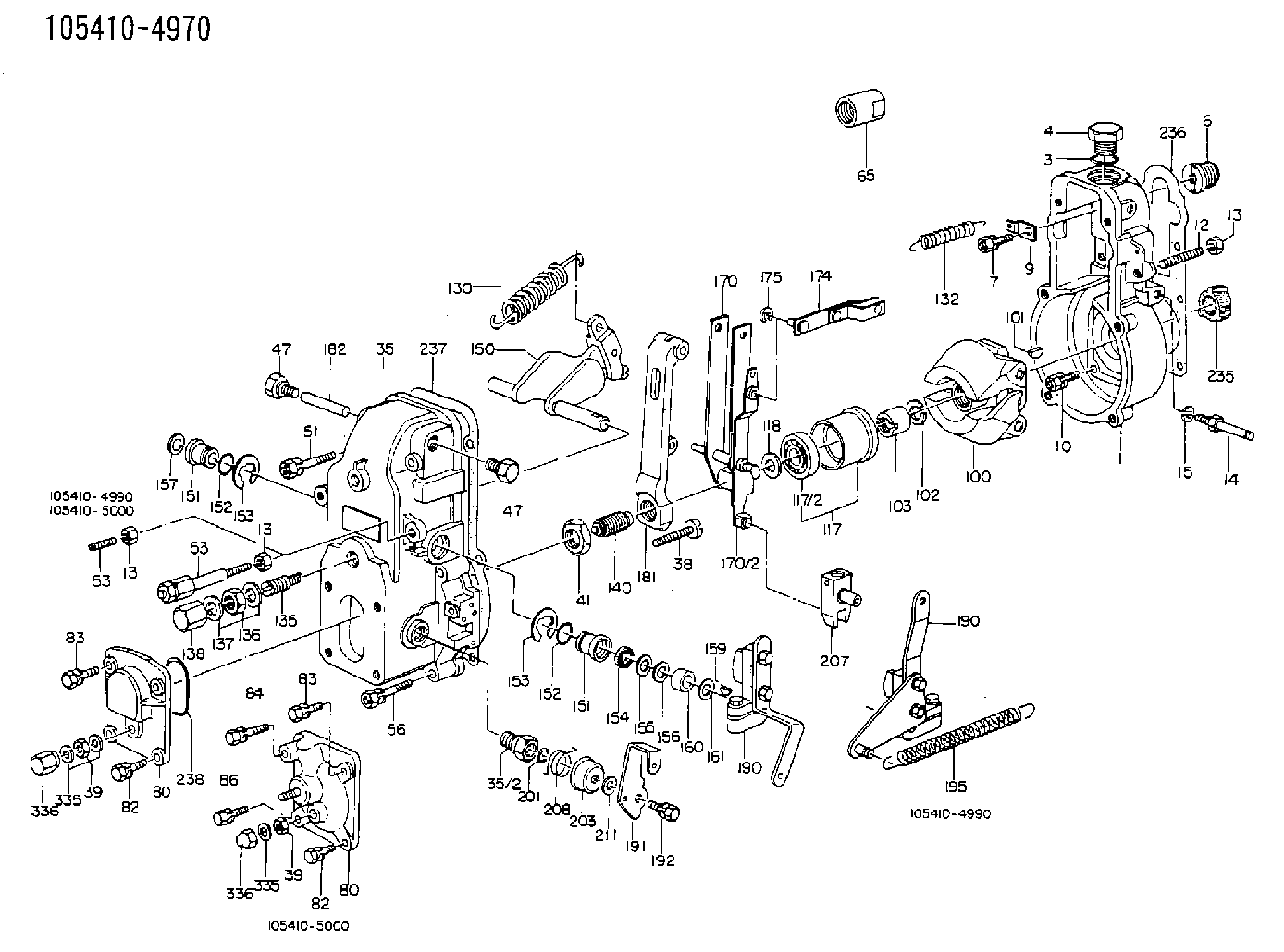
| 1. | [1] | 154004-1400 | GOVERNOR HOUSING |
| 3. | [1] | 029632-5070 | O-RING |
| 4. | [1] | 154007-2900 | CAPSULE |
| 6. | [1] | 154007-0200 | ADAPTOR |
| 7. | [1] | 020018-1840 | BLEEDER SCREW M8P1.25L18 |
| 9. | [1] | 154350-1900 | PLATE |
| 10. | [6] | 029010-6810 | BLEEDER SCREW |
| 12. | [1] | 154010-0100 | FLAT-HEAD SCREW |
| 13. | [2] | 154011-0100 | HEXAGON NUT |
| 13. | [2] | 154011-0100 | HEXAGON NUT |
| 13. | [2] | 154011-0100 | HEXAGON NUT |
| 14. | [1] | 154355-8020 | BRACKET |
| 15. | [1] | 020118-3240 | BLEEDER SCREW |
| 16. | [1] | 029010-5180 | BLEEDER SCREW |
| 17. | [1] | 014110-5440 | LOCKING WASHER |
| 18. | [1] | 154355-8700 | SPACER BUSHING |
| 35. | [1] | 154500-3020 | GOVERNOR COVER |
| 35/2. | [1] | 154321-0400 | BUSHING |
| 38. | [1] | 154031-2400 | FLAT-HEAD SCREW |
| 39. | [1] | 139206-0600 | UNION NUT |
| 39. | [1] | 139206-0600 | UNION NUT |
| 47. | [1] | 154036-0300 | CAPSULE |
| 47. | [1] | 154036-0300 | CAPSULE |
| 51. | [2] | 020106-5040 | BLEEDER SCREW |
| 53. | [1] | 154010-0200 | FLAT-HEAD SCREW |
| 53. | [1] | 154010-0200 | FLAT-HEAD SCREW |
| 56. | [4] | 020106-3840 | BLEEDER SCREW |
| 65. | [1] | 155404-3700 | CAP |
| 80. | [1] | 154063-1400 | COVER |
| 80. | [1] | 154063-1400 | COVER |
| 82. | [2] | 029020-6210 | BLEEDER SCREW |
| 82. | [2] | 029020-6210 | BLEEDER SCREW |
| 83. | [2] | 020006-1640 | BLEEDER SCREW M6P1L16 4T |
| 83. | [2] | 020006-1640 | BLEEDER SCREW M6P1L16 4T |
| 100. | [1] | 154101-0020 | FLYWEIGHT ASSEMBLY |
| 101. | [1] | 025803-1610 | WOODRUFF KEY |
| 102. | [1] | 029321-2020 | LOCKING WASHER |
| 103. | [1] | 029231-2030 | UNION NUT |
| 117. | [1] | 154123-0120 | SLIDING PIECE |
| 118/1. | [0] | 029311-0010 | SHIM D14&10.1T0.2 |
| 118/1. | [0] | 029311-0180 | SHIM D14&10.1T0.3 |
| 118/1. | [0] | 029311-0190 | SHIM D14&10.1T0.40 |
| 118/1. | [0] | 029311-0210 | SHIM D14&10.1T1 |
| 118/1. | [0] | 139410-0000 | SHIM D14.0&10.1T0.5 |
| 118/1. | [0] | 139410-0100 | SHIM D14.0&10.1T1.5 |
| 118/1. | [0] | 139410-3000 | SHIM D14&10.1T2.0 |
| 118/1. | [0] | 139410-3100 | SHIM D14&10.1T3.0 |
| 118/1. | [0] | 139410-3200 | SHIM D14&10.1T4.0 |
| 130. | [1] | 154150-7700 | GOVERNOR SPRING |
| 132. | [1] | 154154-0500 | COILED SPRING |
| 135. | [1] | 154158-1020 | HEADLESS SCREW |
| 136. | [1] | 154011-1700 | UNION NUT |
| 137. | [2] | 026512-1540 | GASKET D15.4&12.2T1.50 |
| 138. | [1] | 154159-1200 | CAP NUT |
| 140. | [1] | 154175-2620 | HEADLESS SCREW |
| 141. | [1] | 029201-6010 | UNION NUT |
| 150. | [1] | 154200-7220 | SWIVELLING LEVER |
| 151. | [1] | 154204-4300 | BUSHING |
| 151. | [1] | 154204-4300 | BUSHING |
| 152. | [2] | 029631-8020 | O-RING |
| 152. | [2] | 029631-8020 | O-RING |
| 153. | [2] | 016010-1640 | LOCKING WASHER |
| 153. | [2] | 016010-1640 | LOCKING WASHER |
| 154. | [1] | 139611-0000 | PACKING RING |
| 155. | [1] | 139411-0000 | SHIM |
| 156. | [0] | 029311-1070 | SHIM D16&11T0.5 |
| 157. | [1] | 154204-4400 | BUSHING |
| 159. | [1] | 025803-1310 | WOODRUFF KEY |
| 160. | [1] | 154206-2800 | BUSHING |
| 161. | [0] | 154206-0200 | PLAIN WASHER D19.5&11.2T1.0 |
| 170. | [1] | 154210-7420 | FORK LEVER |
| 174. | [1] | 154230-3920 | STRAP |
| 175. | [1] | 016010-0540 | LOCKING WASHER |
| 181. | [1] | 154236-1500 | TENSIONING LEVER |
| 182. | [1] | 154237-1100 | BEARING PIN |
| 190. | [1] | 154347-0420 | CONTROL LEVER |
| 190. | [1] | 154347-0420 | CONTROL LEVER |
| 191. | [1] | 154304-9100 | CONTROL LEVER |
| 192. | [1] | 020006-1640 | BLEEDER SCREW M6P1L16 4T |
| 195. | [1] | 154314-9000 | COILED SPRING |
| 201. | [1] | 029631-0030 | O-RING &9.8W2.3 |
| 203. | [1] | 154322-0100 | CAP |
| 207. | [1] | 154326-5120 | CONTROL LEVER |
| 208. | [1] | 154327-7300 | COILED SPRING |
| 211/1. | [0] | 029311-0520 | SHIM D20.8&10.3T0.2 |
| 211/1. | [0] | 029311-0530 | SHIM D20.8&10.3T0.25 |
| 211/1. | [0] | 029311-0540 | SHIM D20.8&10.3T0.3 |
| 211/1. | [0] | 029311-0550 | SHIM D20.8&10.3T0.35 |
| 211/1. | [0] | 029311-0560 | SHIM D20.8&10.3T0.4 |
| 211/1. | [0] | 029311-0570 | SHIM D20.8&10.3T0.5 |
| 235. | [1] | 155412-5200 | IMPELLER WHEEL |
| 236. | [1] | 154390-0000 | GASKET |
| 237. | [1] | 154390-0300 | GASKET |
| 238. | [1] | 029635-2020 | O-RING |
| 335. | [2] | 026506-1040 | GASKET D9.9&6.2T1 |
| 335. | [2] | 026506-1040 | GASKET D9.9&6.2T1 |
| 336. | [1] | 154035-1600 | CAP NUT |
| 336. | [1] | 154035-1600 | CAP NUT |
Cross reference number
Zexel num
Bosch num
Firm num
Name
105410-4970
GOVERNOR
K 14JB MECHANICAL GOVERNOR GOV RSV GOV
K 14JB MECHANICAL GOVERNOR GOV RSV GOV
Information:
3306 Engine Shown1. Turn the fuel supply line valve to the "OFF" position.2. Remove the clamp that holds fuel drain line (1) to the fuel transfer pump. Remove fuel lines (4) and (5).3. Remove bolts (2) and fuel transfer pump (3) from the fuel injection pump housing. Remove the O-ring seal from the fuel transfer pump if necessary.4. Make sure the O-ring seal is in position on the fuel transfer pump. Put the fuel transfer pump in position on the fuel injection pump housing. Install bolts (2) that hold the fuel transfer pump to the fuel injection pump housing.5. Install the clamp that holds fuel drain line (1) to the fuel transfer pump. Install fuel line (4) between the fuel transfer pump and the fuel filter base. Install fuel line (5) between the fuel transfer pump and the fuel priming pump.6. Turn the fuel supply line valve to the "ON" position.Disassemble Fuel Transfer Pump
Start By:a. remove fuel transfer pump
Cover (1) is under spring force. To prevent possible personal injury, carefully remove bolts (2) and cover (1).
1. Remove bolts (2) and cover (1) from the housing. 2. Remove O-ring seals (3) and (4) from the cover.3. Remove valve assembly (5) from the cover. 4. Remove spring (6) from the housing. 5. Remove piston (12) from sleeve (10). Remove washer (15), valve assembly (14) and seal (13) from piston (12).6. Remove sleeve (10) from housing (7). Remove O-ring seal (11) from the sleeve.7. Remove guide and tappet assembly (9) and seal (8) from housing (7). 8. Remove two screws (16), cover (17) and the seal from housing (7). 9. Remove valve assembly (18) from housing (7).Assemble Fuel Transfer Pump
Be sure all parts of the fuel transfer pump are clean before assembly.
1. Install valve assembly (2) in housing (1) as shown. 2. Put clean diesel fuel on seal (2). Put seal (3) in position on cover (4) as shown. Put cover (4) on housing (1). Install the screws that hold the cover. 3. Put clean diesel fuel on seal (5). Put seal (5) and guide and tappet assembly (6) in position in housing (1).4. Put clean diesel fuel on O-ring seal (8). Put O-ring seal (8) in position on sleeve (7). Install sleeve (7) in housing (1).5. Install piston (9) in sleeve (7).6. Put clean diesel fuel on seal (10). Put seal (10), valve assembly (11) and washer (12) in position in piston (7). 7. Put clean diesel fuel on O-ring seals (13) and (14). Put the O-ring seals and valve assembly (15) in position in cover (16) as shown. 8. Put spring (17) and cover (16) in position on housing (1). Install the bolts that hold the spring and cover.End By:a. install fuel transfer pump