Information governor
BOSCH
F 019 Z1E 592
f019z1e592
ZEXEL
105410-4920
1054104920
NISSAN-DIESEL
19109Z7009
19109z7009
Rating:
Scheme ###:
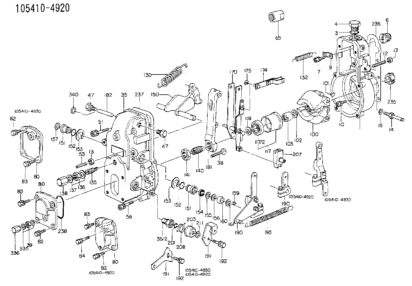
| 1. | [1] | 154000-6400 | GOVERNOR HOUSING |
| 3. | [1] | 029632-5070 | O-RING |
| 4. | [1] | 154007-2900 | CAPSULE |
| 6. | [1] | 154007-0200 | ADAPTOR |
| 7. | [1] | 020018-1840 | BLEEDER SCREW M8P1.25L18 |
| 9. | [1] | 154350-1900 | PLATE |
| 10. | [6] | 029010-6810 | BLEEDER SCREW |
| 12. | [1] | 154010-0100 | FLAT-HEAD SCREW |
| 13. | [2] | 154011-0100 | HEXAGON NUT |
| 13. | [2] | 154011-0100 | HEXAGON NUT |
| 35. | [1] | 154500-3020 | GOVERNOR COVER |
| 35/2. | [1] | 154321-0400 | BUSHING |
| 38. | [1] | 154031-0100 | FLAT-HEAD SCREW |
| 39. | [1] | 013020-6020 | UNION NUT M6P1H5 |
| 47. | [1] | 154036-0300 | CAPSULE |
| 47. | [1] | 154036-0300 | CAPSULE |
| 51. | [2] | 020106-5040 | BLEEDER SCREW |
| 53. | [1] | 154010-0100 | FLAT-HEAD SCREW |
| 56. | [4] | 020106-3840 | BLEEDER SCREW |
| 65. | [1] | 155404-3700 | CAP |
| 80. | [1] | 154060-4900 | COVER |
| 80. | [1] | 154060-4900 | COVER |
| 82. | [2] | 029020-6210 | BLEEDER SCREW |
| 82. | [2] | 029020-6210 | BLEEDER SCREW |
| 83. | [2] | 020006-1640 | BLEEDER SCREW M6P1L16 4T |
| 83. | [2] | 020006-1640 | BLEEDER SCREW M6P1L16 4T |
| 100. | [1] | 154100-4820 | FLYWEIGHT ASSEMBLY |
| 101. | [1] | 025803-1610 | WOODRUFF KEY |
| 102. | [1] | 029321-2020 | LOCKING WASHER |
| 103. | [1] | 029231-2030 | UNION NUT |
| 117. | [1] | 154123-0120 | SLIDING PIECE |
| 118/1. | [0] | 029311-0010 | SHIM D14&10.1T0.2 |
| 118/1. | [0] | 029311-0180 | SHIM D14&10.1T0.3 |
| 118/1. | [0] | 029311-0190 | SHIM D14&10.1T0.40 |
| 118/1. | [0] | 029311-0210 | SHIM D14&10.1T1 |
| 118/1. | [0] | 139410-0000 | SHIM D14.0&10.1T0.5 |
| 118/1. | [0] | 139410-0100 | SHIM D14.0&10.1T1.5 |
| 118/1. | [0] | 139410-3000 | SHIM D14&10.1T2.0 |
| 118/1. | [0] | 139410-3100 | SHIM D14&10.1T3.0 |
| 118/1. | [0] | 139410-3200 | SHIM D14&10.1T4.0 |
| 130. | [1] | 154150-2700 | GOVERNOR SPRING |
| 132. | [1] | 154154-0800 | COILED SPRING |
| 135. | [1] | 154157-0120 | HEADLESS SCREW |
| 136. | [1] | 029201-2030 | UNION NUT M12P1.0H4 |
| 137. | [2] | 026512-1540 | GASKET D15.4&12.2T1.50 |
| 138. | [1] | 154159-1200 | CAP NUT |
| 140. | [1] | 154170-5420 | HEADLESS SCREW |
| 141. | [1] | 029201-6010 | UNION NUT |
| 150. | [1] | 154200-7220 | SWIVELLING LEVER |
| 151. | [1] | 154204-3000 | BUSHING |
| 151. | [1] | 154204-3000 | BUSHING |
| 152. | [2] | 029631-8020 | O-RING |
| 152. | [2] | 029631-8020 | O-RING |
| 153. | [2] | 016010-1640 | LOCKING WASHER |
| 153. | [2] | 016010-1640 | LOCKING WASHER |
| 154. | [1] | 139611-0000 | PACKING RING |
| 155. | [1] | 139411-0000 | SHIM |
| 156. | [0] | 029311-1090 | SHIM D16&11T0.3 |
| 157. | [1] | 154204-3100 | BUSHING |
| 159. | [1] | 025803-1310 | WOODRUFF KEY |
| 160. | [1] | 154206-2800 | BUSHING |
| 161. | [0] | 154206-0200 | PLAIN WASHER D19.5&11.2T1.0 |
| 170. | [1] | 154210-0820 | FORK LEVER |
| 174. | [1] | 154230-3920 | STRAP |
| 175. | [1] | 016010-0540 | LOCKING WASHER |
| 181. | [1] | 154236-1500 | TENSIONING LEVER |
| 182. | [1] | 154237-0100 | BEARING PIN |
| 190. | [1] | 154340-0020 | CONTROL LEVER |
| 190. | [1] | 154340-0020 | CONTROL LEVER |
| 191. | [1] | 154308-3720 | CONTROL LEVER |
| 191. | [1] | 154308-3720 | CONTROL LEVER |
| 192. | [1] | 020006-1640 | BLEEDER SCREW M6P1L16 4T |
| 192. | [1] | 020006-1640 | BLEEDER SCREW M6P1L16 4T |
| 201. | [1] | 029631-0030 | O-RING &9.8W2.3 |
| 203. | [1] | 154322-0100 | CAP |
| 207. | [1] | 154326-5120 | CONTROL LEVER |
| 208. | [1] | 154327-7300 | COILED SPRING |
| 211/1. | [0] | 029311-0520 | SHIM D20.8&10.3T0.2 |
| 211/1. | [0] | 029311-0530 | SHIM D20.8&10.3T0.25 |
| 211/1. | [0] | 029311-0540 | SHIM D20.8&10.3T0.3 |
| 211/1. | [0] | 029311-0550 | SHIM D20.8&10.3T0.35 |
| 211/1. | [0] | 029311-0560 | SHIM D20.8&10.3T0.4 |
| 211/1. | [0] | 029311-0570 | SHIM D20.8&10.3T0.5 |
| 236. | [1] | 154390-0000 | GASKET |
| 237. | [1] | 154390-0300 | GASKET |
| 238. | [1] | 029635-2020 | O-RING |
| 340. | [1] | 154036-0700 | CAPSULE |
Include in #1:
101331-9123
as GOVERNOR
Cross reference number
Zexel num
Bosch num
Firm num
Name
105410-4920
F 019 Z1E 592
19109Z7009 NISSAN-DIESEL
GOVERNOR
* K
* K
Information:
Start By:a. remove fuel injection lines 1. Remove bolt (1) and clamp (2) from the fuel injection nozzles to be removed.2. Install Tool (A) with the inside lip of the puller on the lower stepped diameter of the nozzle and the tip of the button in the threaded hole for bolt (1).
Do not exceed a torque of 17 N m (150 lb in) on the screw of Tool (A) during removal of the nozzle. Added force can cause the stem of the nozzle to bend or break off.
3. Tighten the screw of Tool (A) to a maximum torque of 17 N m (150 lb in) to remove fuel injection nozzle (3).4. If the fuel injection nozzle can not be removed with a maximum torque of 17 N m (150 lb in) on the screw of Tool (A), remove Tool (A).
Typical Example5. Remove the protective cap from fuel injection nozzle (3), and install Tool (B) as shown.
Hold Tool (B) so the center line of the tool is in alignment with the centerline of fuel injection nozzle (3). This will prevent distortion of the nozzle which can cause it to bend or break off during removal.
6. Remove the fuel injection nozzle with Tool (B).7. If Tool (B) was used to remove the fuel injection nozzle, replace the nozzle.8. If Tool (A) was used to remove the fuel injection nozzle, remove the carbon dam seal on the end of the nozzle.Install Fuel Injection Nozzle
1. Use Tool (C) to clean the bore for the fuel injection nozzle. Use an open end wrench or tap driver to turn Tool (C).2. Make reference to Special Instruction, Form No. SEHS7292, for the use of Tool (D). Clean the fuel injection nozzle with Tool (D). 3. Install a new seal (4) on fuel injection nozzle (3).4. Put carbon dam seal (5) on the small end of Tool (E). Expand the carbon dam seal by sliding it to the large end. Put Tool (E) against the fuel injection nozzle. Slide carbon dam seal (5) off Tool (E) on to the nozzle. Slide the carbon dam seal into position in the groove on the nozzle as shown. 5. Put fuel injection nozzle (3) in position in the cylinder head. Install clamp (2) and bolt (1) to hold the nozzle in position.End By:a. install fuel injection lines
Have questions with 105410-4920?
Group cross 105410-4920 ZEXEL
Ishikawajima-S
Nissan-Diesel
105410-4920
F 019 Z1E 592
19109Z7009
GOVERNOR