Information governor
BOSCH
F 019 Z1E 058
f019z1e058
ZEXEL
105410-4141
1054104141
ISUZU
1157204130
1157204130
Rating:
Scheme ###:
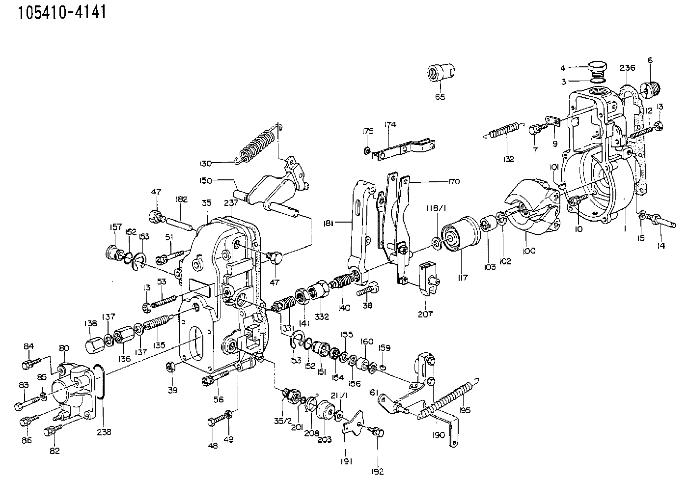
| 1. | [1] | 154000-6400 | GOVERNOR HOUSING |
| 3. | [1] | 029632-5070 | O-RING |
| 4. | [1] | 154007-2900 | CAPSULE |
| 6. | [1] | 154007-0200 | ADAPTOR |
| 7. | [1] | 020018-1840 | BLEEDER SCREW M8P1.25L18 |
| 9. | [1] | 154350-1900 | PLATE |
| 10. | [6] | 029010-6810 | BLEEDER SCREW |
| 12. | [1] | 154010-0100 | FLAT-HEAD SCREW |
| 13. | [2] | 154011-0100 | HEXAGON NUT |
| 13. | [2] | 154011-0100 | HEXAGON NUT |
| 14. | [1] | 154012-1500 | BLEEDER SCREW |
| 15. | [1] | 014110-8440 | LOCKING WASHER |
| 35. | [1] | 154500-3720 | GOVERNOR COVER |
| 35/2. | [1] | 154321-0400 | BUSHING |
| 38. | [1] | 154031-0100 | FLAT-HEAD SCREW |
| 39. | [1] | 013020-6020 | UNION NUT M6P1H5 |
| 47. | [2] | 154036-0300 | CAPSULE |
| 47. | [2] | 154036-0300 | CAPSULE |
| 48. | [1] | 154037-0700 | BLEEDER SCREW |
| 49. | [1] | 154038-0200 | HEXAGON NUT |
| 51. | [2] | 020106-5040 | BLEEDER SCREW |
| 53. | [1] | 154010-0200 | FLAT-HEAD SCREW |
| 56. | [4] | 020106-3840 | BLEEDER SCREW |
| 65. | [1] | 155404-0200 | CAP |
| 80. | [1] | 154063-1220 | COVER |
| 82. | [1] | 020006-1640 | BLEEDER SCREW M6P1L16 4T |
| 83. | [1] | 020006-1640 | BLEEDER SCREW M6P1L16 4T |
| 84. | [1] | 029020-6250 | BLEEDER SCREW |
| 85. | [1] | 014110-6440 | LOCKING WASHER |
| 86. | [1] | 020006-1640 | BLEEDER SCREW M6P1L16 4T |
| 100. | [1] | 154100-4020 | FLYWEIGHT ASSEMBLY |
| 101. | [1] | 025803-1610 | WOODRUFF KEY |
| 102. | [1] | 029321-2020 | LOCKING WASHER |
| 103. | [1] | 029231-2030 | UNION NUT |
| 117. | [1] | 154123-0120 | SLIDING PIECE |
| 118/1. | [0] | 029311-0010 | SHIM D14&10.1T0.2 |
| 118/1. | [0] | 029311-0180 | SHIM D14&10.1T0.3 |
| 118/1. | [0] | 029311-0190 | SHIM D14&10.1T0.40 |
| 118/1. | [0] | 029311-0210 | SHIM D14&10.1T1 |
| 118/1. | [0] | 139410-0000 | SHIM D14.0&10.1T0.5 |
| 118/1. | [0] | 139410-0100 | SHIM D14.0&10.1T1.5 |
| 118/1. | [0] | 139410-3000 | SHIM D14&10.1T2.0 |
| 118/1. | [0] | 139410-3100 | SHIM D14&10.1T3.0 |
| 118/1. | [0] | 139410-3200 | SHIM D14&10.1T4.0 |
| 130. | [1] | 154150-0400 | GOVERNOR SPRING |
| 132. | [1] | 154154-0701 | COILED SPRING |
| 135. | [1] | 154158-0920 | HEADLESS SCREW |
| 136. | [1] | 154011-1700 | UNION NUT |
| 137. | [2] | 026512-1540 | GASKET D15.4&12.2T1.50 |
| 137. | [2] | 026512-1540 | GASKET D15.4&12.2T1.50 |
| 138. | [1] | 154159-1200 | CAP NUT |
| 140. | [1] | 154185-1220 | HEADLESS SCREW |
| 141. | [1] | 029201-6080 | UNION NUT |
| 150. | [1] | 154200-6920 | SWIVELLING LEVER |
| 151. | [1] | 154204-4300 | BUSHING |
| 152. | [2] | 029631-8020 | O-RING |
| 152. | [2] | 029631-8020 | O-RING |
| 153. | [2] | 016010-1640 | LOCKING WASHER |
| 153. | [2] | 016010-1640 | LOCKING WASHER |
| 154. | [1] | 139611-0000 | PACKING RING |
| 155. | [1] | 139411-0000 | SHIM |
| 156. | [0] | 029311-1070 | SHIM D16&11T0.5 |
| 157. | [1] | 154204-4400 | BUSHING |
| 159. | [1] | 025803-1310 | WOODRUFF KEY |
| 160. | [1] | 154206-2800 | BUSHING |
| 161. | [0] | 154206-0200 | PLAIN WASHER D19.5&11.2T1.0 |
| 170. | [1] | 154210-7420 | FORK LEVER |
| 174. | [1] | 154230-3920 | STRAP |
| 175. | [1] | 016010-0540 | LOCKING WASHER |
| 181. | [1] | 154236-4100 | TENSIONING LEVER |
| 182. | [1] | 154237-0100 | BEARING PIN |
| 190. | [1] | 154342-1420 | CONTROL LEVER |
| 191. | [1] | 154308-4100 | CONTROL LEVER |
| 192. | [1] | 020006-1640 | BLEEDER SCREW M6P1L16 4T |
| 195. | [1] | 154314-0200 | COILED SPRING |
| 201. | [1] | 029631-0030 | O-RING &9.8W2.3 |
| 203. | [1] | 154322-0100 | CAP |
| 207. | [1] | 154326-5120 | CONTROL LEVER |
| 208. | [1] | 154327-7300 | COILED SPRING |
| 211/1. | [0] | 029311-0520 | SHIM D20.8&10.3T0.2 |
| 211/1. | [0] | 029311-0530 | SHIM D20.8&10.3T0.25 |
| 211/1. | [0] | 029311-0540 | SHIM D20.8&10.3T0.3 |
| 211/1. | [0] | 029311-0550 | SHIM D20.8&10.3T0.35 |
| 211/1. | [0] | 029311-0560 | SHIM D20.8&10.3T0.4 |
| 211/1. | [0] | 029311-0570 | SHIM D20.8&10.3T0.5 |
| 236. | [1] | 154390-0000 | GASKET |
| 237. | [1] | 154390-0300 | GASKET |
| 238. | [1] | 029635-2020 | O-RING |
| 331. | [1] | 154172-3520 | HEADLESS SCREW |
| 332. | [1] | 029201-6010 | UNION NUT |
Include in #1:
101602-0360
as GOVERNOR
Cross reference number
Zexel num
Bosch num
Firm num
Name
Information:
Tighten locknuts (A) on rod ends to ... 12 4 N m (9 3 lb ft)With governor at High Idle, install lever (B) on governor shaft at an angle from vertical of ... 20 5°Dimension (C) approximately ... 438.0 mm (17.25 in)Dimension (D) approximately ... 597.0 mm (23.50 in)Dimension (E) approximately ... 610.0 mm (24.00 in)Dimension (F) approximately ... 100.00 mm (3.94 in)Dimension (G) ... 1.5 mm (.06 in)Adjust bolt (H) to get dimension (F) with engine at High IdleAdjust setscrew (J) so that engine speed is 985 50 rpm with decelerator pedal depressed. Check High Idle speed after adjustment.After linkage has been adjusted, move control lever to High Idle and adjust setscrew (K) to get dimension (G).D7G With Direct Drive Transmission & 571G Pipelayer
Tighten locknuts (A) on ends to ... 12 4 N m (9 3 lb ft)With governor at High Idle, install lever (B) on governor shaft at an angle from vertical of ... 20 5°Dimension (C) approximately ... 438.0 mm (17.25 in)Dimension (D) approximately ... 597.0 mm (23.50 in)572G Pipelayer
Tighten locknuts (A) on rod ends to ... 12 4 N m (9 3 lb ft)With governor at High Idle, install lever (B) on governor shaft at an angle from vertical of ... 5° 5°Dimension (C) approximately ... 726.4 mm (28.6 in)Dimension (D) approximately ... 683.3 mm (26.9 in)7G5554 Control Group (D6H)
1. Tighten locknuts (A) on rod ends to ... 14 4 N m (10 3 lb ft)2. Align the timing mark on shaft (B) with centerline of sawcut on lever (C).3. Dimension (D) approximately ... 508 mm (20 in)4. With governor control lever in a vertical position, angle (E) ... 32° 5°3T4347 Control Group (D6H)
1. Tighten locknuts (A) on rod ends to ... 14 4 N m (10 3 lb ft)2. Align the timing mark on shaft (B) with centerline of sawcut on lever (C).3. Dimension (D) approximately ... 508 mm (20 in)4. With governor control lever in a vertical position, angle (E) ... 32° 5°6T3303 Control Group (D7H)
1. Tighten locknuts (A) on rod ends to ... 12 4 N m (9 3 lb ft)2. Align the timing mark on shaft (B) with centerline of sawcut on lever (C).3. With governor control lever in a vertical position, angle (E) ... 32° 5°8P3126 Control Group (D5B SA)
1. With control lever (1) in high idle position Dimension (A) approximately ... 495.0 mm (19.5 in)Dimension (B) approximately ... 786.0 mm (30.9 in)Angle (C) from vertical ... 10° 5°2. Tighten locknuts (2) on rod ends to ... 25 7 N m (18 5 lb ft)3. Tighten locknuts (3) on rod ends to ... 12 4 N m (9 3 lb ft)9W3764 Control Group (D6D SA)
1. With control lever (1) in high idle position Dimension (A) approximately ... 495.0 3.0 mm (19.5 .1 in)Dimension (B) approximately ... 735.0 mm (28.9 in)Angle (C) from vertical