Information governor
BOSCH
F 019 Z1E 035
f019z1e035
ZEXEL
105410-2670
1054102670
Rating:
Scheme ###:
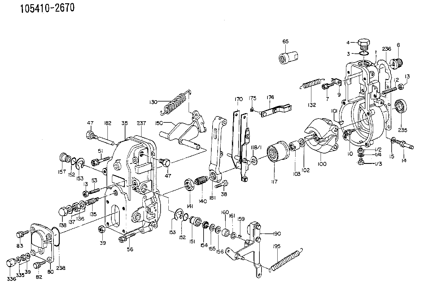
| 1. | [1] | 154000-6400 | GOVERNOR HOUSING |
| 3. | [1] | 029632-5070 | O-RING |
| 4. | [1] | 154007-2900 | CAPSULE |
| 6. | [1] | 154007-0200 | ADAPTOR |
| 7. | [1] | 020018-1840 | BLEEDER SCREW M8P1.25L18 |
| 9. | [1] | 154350-1900 | PLATE |
| 10. | [6] | 029010-6810 | BLEEDER SCREW |
| 12. | [1] | 154010-0100 | FLAT-HEAD SCREW |
| 13. | [2] | 154011-0100 | HEXAGON NUT |
| 13. | [2] | 154011-0100 | HEXAGON NUT |
| 14. | [1] | 154012-1500 | BLEEDER SCREW |
| 15. | [1] | 014110-8440 | LOCKING WASHER |
| 35. | [1] | 154500-2020 | GOVERNOR COVER |
| 38. | [1] | 154031-2400 | FLAT-HEAD SCREW |
| 39. | [1] | 139206-0600 | UNION NUT |
| 39. | [1] | 139206-0600 | UNION NUT |
| 47. | [2] | 154036-0300 | CAPSULE |
| 47. | [2] | 154036-0300 | CAPSULE |
| 51. | [2] | 020106-5040 | BLEEDER SCREW |
| 53. | [1] | 154010-0100 | FLAT-HEAD SCREW |
| 56. | [4] | 020106-3840 | BLEEDER SCREW |
| 65. | [1] | 155404-0200 | CAP |
| 80. | [1] | 154063-1400 | COVER |
| 82. | [2] | 029020-6210 | BLEEDER SCREW |
| 83. | [2] | 020006-1640 | BLEEDER SCREW M6P1L16 4T |
| 100. | [1] | 154100-3220 | FLYWEIGHT ASSEMBLY |
| 101. | [1] | 025803-1610 | WOODRUFF KEY |
| 102. | [1] | 029321-2020 | LOCKING WASHER |
| 103. | [1] | 029231-2030 | UNION NUT |
| 117. | [1] | 154123-0120 | SLIDING PIECE |
| 118/1. | [0] | 029311-0010 | SHIM D14&10.1T0.2 |
| 118/1. | [0] | 029311-0180 | SHIM D14&10.1T0.3 |
| 118/1. | [0] | 029311-0190 | SHIM D14&10.1T0.40 |
| 118/1. | [0] | 029311-0210 | SHIM D14&10.1T1 |
| 118/1. | [0] | 139410-0000 | SHIM D14.0&10.1T0.5 |
| 118/1. | [0] | 139410-0100 | SHIM D14.0&10.1T1.5 |
| 118/1. | [0] | 139410-3000 | SHIM D14&10.1T2.0 |
| 118/1. | [0] | 139410-3100 | SHIM D14&10.1T3.0 |
| 118/1. | [0] | 139410-3200 | SHIM D14&10.1T4.0 |
| 130. | [1] | 154150-0400 | GOVERNOR SPRING |
| 132. | [1] | 154154-0800 | COILED SPRING |
| 135. | [1] | 154157-0320 | HEADLESS SCREW |
| 136. | [1] | 029201-2030 | UNION NUT M12P1.0H4 |
| 137. | [2] | 026512-1540 | GASKET D15.4&12.2T1.50 |
| 138. | [1] | 154159-1200 | CAP NUT |
| 140. | [1] | 154177-0620 | HEADLESS SCREW |
| 141. | [1] | 029201-6010 | UNION NUT |
| 150. | [1] | 154200-6920 | SWIVELLING LEVER |
| 151. | [1] | 154204-4300 | BUSHING |
| 152. | [2] | 029631-8020 | O-RING |
| 152. | [2] | 029631-8020 | O-RING |
| 153. | [2] | 016010-1640 | LOCKING WASHER |
| 153. | [2] | 016010-1640 | LOCKING WASHER |
| 154. | [1] | 139611-0000 | PACKING RING |
| 155. | [1] | 139411-0000 | SHIM |
| 156. | [0] | 029311-1070 | SHIM D16&11T0.5 |
| 157. | [1] | 154204-4400 | BUSHING |
| 159. | [1] | 025803-1310 | WOODRUFF KEY |
| 160. | [1] | 154206-2800 | BUSHING |
| 161. | [0] | 154206-0200 | PLAIN WASHER D19.5&11.2T1.0 |
| 170. | [1] | 154211-3820 | FORK LEVER |
| 174. | [1] | 154230-0120 | STRAP |
| 175. | [1] | 016010-0540 | LOCKING WASHER |
| 181. | [1] | 154236-4100 | TENSIONING LEVER |
| 182. | [1] | 154237-0100 | BEARING PIN |
| 190. | [1] | 154303-5220 | CONTROL LEVER |
| 195. | [1] | 154314-0200 | COILED SPRING |
| 236. | [1] | 154390-0000 | GASKET |
| 237. | [1] | 154390-0300 | GASKET |
| 238. | [1] | 029635-2020 | O-RING |
| 335. | [2] | 026506-1040 | GASKET D9.9&6.2T1 |
| 336. | [1] | 154035-1600 | CAP NUT |
Include in #1:
101685-0320
as GOVERNOR
Cross reference number
Zexel num
Bosch num
Firm num
Name
105410-2670
F 019 Z1E 035
GOVERNOR
* K
* K
Information:
Model Views
The sample model view drawings show various typical Caterpillar 3408C and 3412C Engine features. The drawings are generic and do not reflect all available options. Because of individual applications, your engine may appear different from those illustrated.
3408 Model Views:(1) Exhaust(2) Oil Level Gauge (Dipstick)(3) Crankcase Breather(4) Oil Filler Cap(5) Manual Shutoff Shaft(6) Lifting Eye(7) Fuel Priming Pump(8) Fuel Pressure Gauge(9) Fuel Filter(10) Oil Filter(11) Supplemental Coolant Additive Element(12) Oil Drain(13) Air Inlet(14) Turbocharger(15) and Magnetic Pickup Location.
3412 Model Views:(1) Exhaust(2) Oil Level Gauge (Dipstick)(3) Crankcase Breather(4) Oil Filler Cap(5) Manual Shutoff Shaft(6) Lifting Eye(7) Fuel Priming Pump(8) Fuel Pressure Gauge(9) Fuel Filter(10) Oil Filter(11) Supplemental Coolant Additive Element(12) Oil Drain(13) Air Inlet(14) Turbocharger
Typical Generator Set (3408 Shown):(1) Control and Power Panel(2) Exhaust(3) Crankcase Breather(4) Oil Filler Cap(5) Governor Control Lever(6) Manual Shutoff Shaft(7) Radiator Cap(8) Lifting Location(9) Generator(10) Fuel Priming Pump(11) Fuel Filter(12) Oil Level Gauge (Dipstick)(13) Oil Filter(14) and Radiator DrainEngine Information
Engine Descriptions
The Caterpillar 3408C and 3412C Industrial Engines are available as precombustion chamber engines or as direct injection engines.A mechanical governor controls the fuel injection pump output, maintaining the engine rpm selected by the operator. Individual injection pumps (one for each cylinder) meter and pump fuel under high pressure to injection nozzles. Automatic timing advance provides the best fuel injection timing over the full range of engine speed.The fuel ratio control is located on the governor. The fuel ratio control restricts the fuel rack movement. Only the proper amount of fuel is allowed to be injected into the cylinders during acceleration. This minimizes exhaust smoke.Inlet air is filtered by an air cleaner. The air is compressed by a turbocharger before the air enters the engine cylinders. The turbocharger is driven by engine exhaust. The engines can be turbocharged, or turbocharged with jacket water aftercooling.The engines are four cycle engines. Each cylinder head has two inlet valves and two exhaust valves. The rocker arms and the valves are actuated by the camshaft. The action is performed by mechanical lifters and push rods.The cooling system consists of:* two thermostats (one for each bank) to regulate water temperature.* a gear driven centrifugal pump.* an oil cooler, and* a radiator (incorporating a shunt system).The engine lubricating oil, which is both cooled and filtered, is supplied by a gear-type pump. Bypass valves provide unrestricted flow of lubrication oil to the engine parts if oil viscosity is high, or if the oil cooler or the oil filter elements become plugged.Engine efficiency, efficiency of emission controls, and engine performance depend on adherence to proper operation and maintenance recommendations. Engine performance and efficiency also depend on the use of recommended coolant/antifreeze, fuels, and lubrication oils. Follow the recommended Maintenance Schedule found in this publication, paying attention to emission related components, air cleaner, oil, oil filter, fuel and fuel filter maintenance.EPG Information
Caterpillar Electrical Power Generation (EPG) Diesel Engines may be equipped with the Electronic Modular Control Panel II (EMCPII) and the SR4B Generator.The EMCPII provides accurate and reliable engine and generator control and monitoring.
Have questions with 105410-2670?
Group cross 105410-2670 ZEXEL
Isuzu
Isuzu
105410-2670
F 019 Z1E 035
GOVERNOR