Information governor
BOSCH
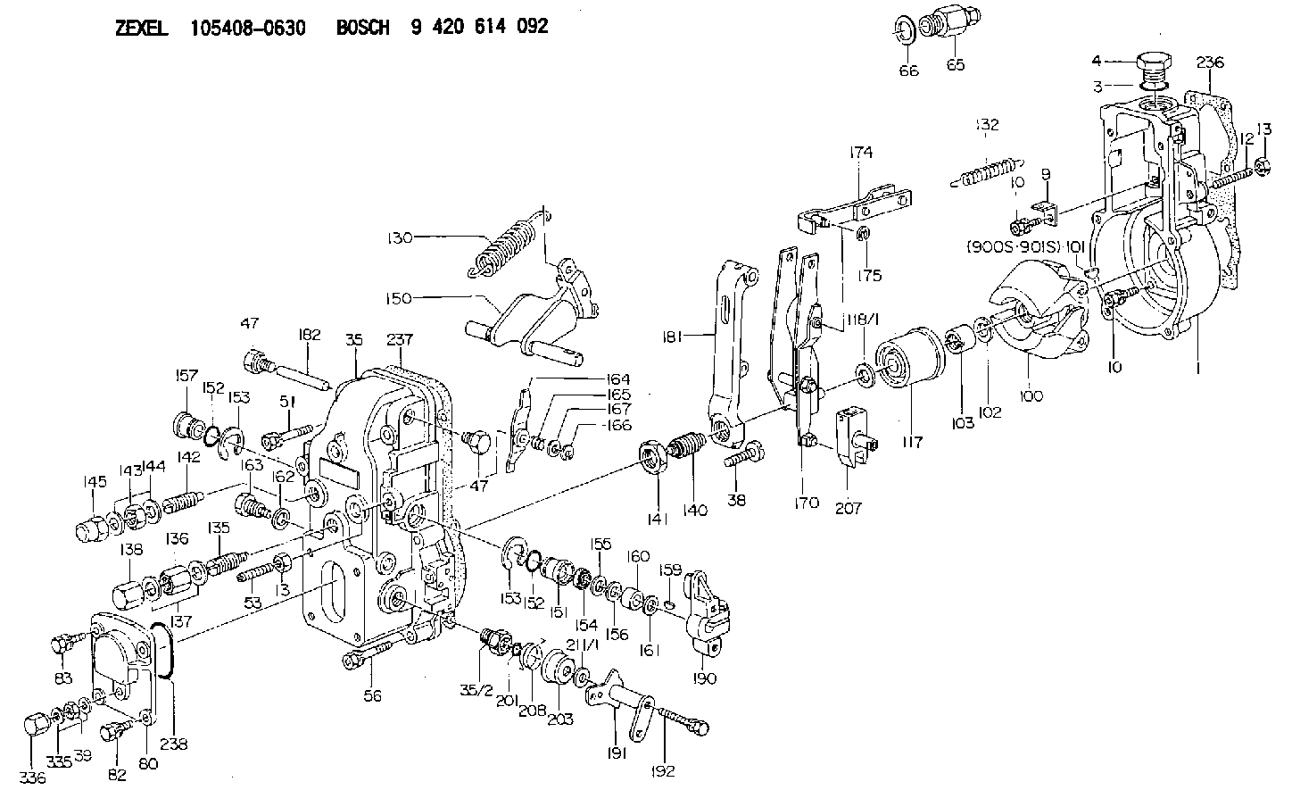
9 420 614 092
9420614092
ZEXEL
105408-0630
1054080630
MITSUBISHI
ME730207
me730207
Rating:
Scheme ###:
| 1. | [1] | 154000-4700 | GOVERNOR HOUSING |
| 3. | [1] | 029632-5070 | O-RING |
| 4. | [1] | 154007-2900 | CAPSULE |
| 9. | [1] | 154350-6000 | PLATE |
| 10. | [8] | 020106-2040 | BLEEDER SCREW M6P1L20 |
| 10. | [8] | 020106-2040 | BLEEDER SCREW M6P1L20 |
| 12. | [1] | 154010-1100 | FLAT-HEAD SCREW |
| 13. | [2] | 154011-0100 | HEXAGON NUT |
| 13. | [2] | 154011-0100 | HEXAGON NUT |
| 35. | [1] | 154500-3320 | GOVERNOR COVER |
| 35/2. | [1] | 154321-0400 | BUSHING |
| 38. | [1] | 154031-2400 | FLAT-HEAD SCREW |
| 39. | [1] | 139206-0600 | UNION NUT |
| 47. | [2] | 154036-0300 | CAPSULE |
| 47. | [2] | 154036-0300 | CAPSULE |
| 51. | [2] | 020106-5040 | BLEEDER SCREW |
| 53. | [1] | 154010-0100 | FLAT-HEAD SCREW |
| 56. | [4] | 020106-3840 | BLEEDER SCREW |
| 65. | [1] | 153021-2220 | STOPPING DEVICE |
| 66. | [1] | 026524-3040 | GASKET |
| 80. | [1] | 154063-1400 | COVER |
| 82. | [2] | 029020-6210 | BLEEDER SCREW |
| 83. | [2] | 020006-1640 | BLEEDER SCREW M6P1L16 4T |
| 100. | [1] | 154101-0020 | FLYWEIGHT ASSEMBLY |
| 101. | [1] | 025803-1310 | WOODRUFF KEY |
| 102. | [1] | 029321-2020 | LOCKING WASHER |
| 103. | [1] | 029231-2030 | UNION NUT |
| 117. | [1] | 154123-2320 | SLIDING PIECE |
| 118/1. | [0] | 029311-0010 | SHIM D14&10.1T0.2 |
| 118/1. | [0] | 029311-0180 | SHIM D14&10.1T0.3 |
| 118/1. | [0] | 029311-0190 | SHIM D14&10.1T0.40 |
| 118/1. | [0] | 029311-0210 | SHIM D14&10.1T1 |
| 118/1. | [0] | 139410-0000 | SHIM D14.0&10.1T0.5 |
| 118/1. | [0] | 139410-0100 | SHIM D14.0&10.1T1.5 |
| 118/1. | [0] | 139410-3000 | SHIM D14&10.1T2.0 |
| 118/1. | [0] | 139410-3100 | SHIM D14&10.1T3.0 |
| 118/1. | [0] | 139410-3200 | SHIM D14&10.1T4.0 |
| 130. | [1] | 154150-0400 | GOVERNOR SPRING |
| 132. | [1] | 154154-0500 | COILED SPRING |
| 135. | [1] | 154158-0820 | HEADLESS SCREW |
| 136. | [1] | 154011-1700 | UNION NUT |
| 137. | [2] | 026512-1540 | GASKET D15.4&12.2T1.50 |
| 138. | [1] | 154159-1200 | CAP NUT |
| 140. | [1] | 154177-1520 | HEADLESS SCREW |
| 141. | [1] | 029201-6010 | UNION NUT |
| 142. | [1] | 154242-0620 | HEADLESS SCREW |
| 143. | [1] | 029201-6150 | UNION NUT |
| 144. | [2] | 026516-2040 | GASKET D19.9&16.2T1 |
| 145. | [1] | 154159-1100 | CAP NUT |
| 150. | [1] | 154200-6920 | SWIVELLING LEVER |
| 151. | [1] | 154204-3000 | BUSHING |
| 152. | [2] | 029631-8020 | O-RING |
| 152. | [2] | 029631-8020 | O-RING |
| 153. | [2] | 016010-1640 | LOCKING WASHER |
| 153. | [2] | 016010-1640 | LOCKING WASHER |
| 154. | [1] | 139611-0000 | PACKING RING |
| 155. | [1] | 139411-0000 | SHIM |
| 156. | [0] | 029311-1070 | SHIM D16&11T0.5 |
| 157. | [1] | 154204-3100 | BUSHING |
| 159. | [1] | 025803-1310 | WOODRUFF KEY |
| 160. | [1] | 154206-2800 | BUSHING |
| 161. | [0] | 154206-0200 | PLAIN WASHER D19.5&11.2T1.0 |
| 162. | [1] | 029331-0240 | GASKET |
| 163. | [1] | 154401-2700 | BLEEDER SCREW |
| 164. | [1] | 154243-0220 | CONTROL LEVER |
| 165. | [1] | 154327-1900 | COILED SPRING |
| 166. | [1] | 016010-0710 | LOCKING WASHER |
| 167. | [1] | 029310-8020 | PLAIN WASHER D15&8.4T0.3 |
| 170. | [1] | 154211-4320 | FORK LEVER |
| 174. | [1] | 154230-2920 | STRAP |
| 175. | [1] | 016010-0540 | LOCKING WASHER |
| 181. | [1] | 154236-3220 | TENSIONING LEVER |
| 182. | [1] | 154237-0100 | BEARING PIN |
| 190. | [1] | 154340-0120 | CONTROL LEVER |
| 191. | [1] | 154364-3420 | CONTROL LEVER |
| 192. | [1] | 020006-4540 | BLEEDER SCREW M6P1L45 |
| 201. | [1] | 029631-0030 | O-RING &9.8W2.3 |
| 203. | [1] | 154322-0100 | CAP |
| 207. | [1] | 154326-5120 | CONTROL LEVER |
| 208. | [1] | 154327-7300 | COILED SPRING |
| 211/1. | [0] | 029311-0520 | SHIM D20.8&10.3T0.2 |
| 211/1. | [0] | 029311-0530 | SHIM D20.8&10.3T0.25 |
| 211/1. | [0] | 029311-0540 | SHIM D20.8&10.3T0.3 |
| 211/1. | [0] | 029311-0550 | SHIM D20.8&10.3T0.35 |
| 211/1. | [0] | 029311-0560 | SHIM D20.8&10.3T0.4 |
| 211/1. | [0] | 029311-0570 | SHIM D20.8&10.3T0.5 |
| 236. | [1] | 154371-5600 | GASKET |
| 237. | [1] | 154390-0300 | GASKET |
| 238. | [1] | 029635-2020 | O-RING |
| 335. | [2] | 026506-1040 | GASKET D9.9&6.2T1 |
| 336. | [1] | 154035-1600 | CAP NUT |
| 900S. | [1] | 025803-1310 | WOODRUFF KEY |
| 901S. | [1] | 025803-1610 | WOODRUFF KEY |
Cross reference number
Zexel num
Bosch num
Firm num
Name
Information:
Installation of Nozzles, Ether Supply Tubes and Connectors
1. If the machine does not already have an ether aid starting system, remove the plug from each turbocharger outlet adapter (2) and (3). Install a 3B6768 Bushing with a 7X1078 Nozzle Assembly (1) where each plug was removed. 2. When installing each nozzle assembly (1), the indicator mark at location (A) must be at the top as shown. Tighten the nozzle to a torque of 2.8 N m (25 lb in).3. Install 6Y1575 Tube Assembly (4) in the front nozzle and 6Y1576 Tube Assembly (6) in the rear nozzle as shown. Connect tube assemblies (4) and (6) to 8C9006 Tee (5). 4. Put 6Y1770 Tube Assembly (7) in position along the cylinder block and connect it to 8C9006 Tee (5) as shown. Install a 5P6312 Union (8) at the loose end as shown.5. Locate and attach 6V2686 Clips at locations (B) and (C), to secure tube (7) in position.6. Tighten the bolts that secure the clips at locations (B) and (C). 7. Put 5P0580 Tube (9) in position for connection to 5P6312 Union (8) that was JUST installed at the end of tube assembly (7). Position the tube assembly alongside chassis wiring harness (10) and up to the shuttle valve in cover assembly (11).Cut the 5P0580 Tube to length. Put a 5P6313 Nut and a 5P6314 Sleeve on the end of the piece of tube. Connect the end of the tube to union (8) and tighten the nut.
Be careful and DO NOT overtighten the nut. Overtightening the nut could crush the tube.
8. Use 3S2093 Straps (12) to fasten tube (9) to chassis wiring harness (10) [there are actually twelve straps between union (8) and the fender, and three straps inside of cover assembly (11)]. 9. Connect the end of tube (9) to elbow (13) in the outlet port of the shuttle valve. 10. If all welding procedures have been completed proceed as follows: * Apply the 9X4542 Ether Aid Identification Film (English) on the ECU. (If an Ether Aid Identification Film is needed for a language other than English, refer to the chart that follows for the part number to order to obtain a film with a specific language.) * Use four 5M3062 Bolts with 8T4896 Washers to fasten 9X5303 ECU (14) to the mounting bars inside cover assembly (11).* Connect the terminal on the loose end of fabricated wire assembly (15) (previously installed when mounting bars were installed inside the cover assembly) to one of the ECU mounting bolts as shown.* Connect the 30 pin connector of chassis wiring harness (10) to ECU (14).11. Use the dimensions shown to install 9X6191 Film (16).12. Put a 5P1075 Washer over the end of the 7S2043 Knob Assembly. Put the end of the knob assembly through the door of cover assembly (11). Install the 9S8230 Plate Assembly over the shaft of the knob assembly, then insert the 4H1641 Pin in the hole in the shaft.Installation of Ether Cylinders
1. Turn the disconnect switch