Information governor
BOSCH
F 019 Z4E 400
f019z4e400
ZEXEL
105407-8340
1054078340
MITSUBISHI
ME755955
me755955

Rating:
Scheme ###:
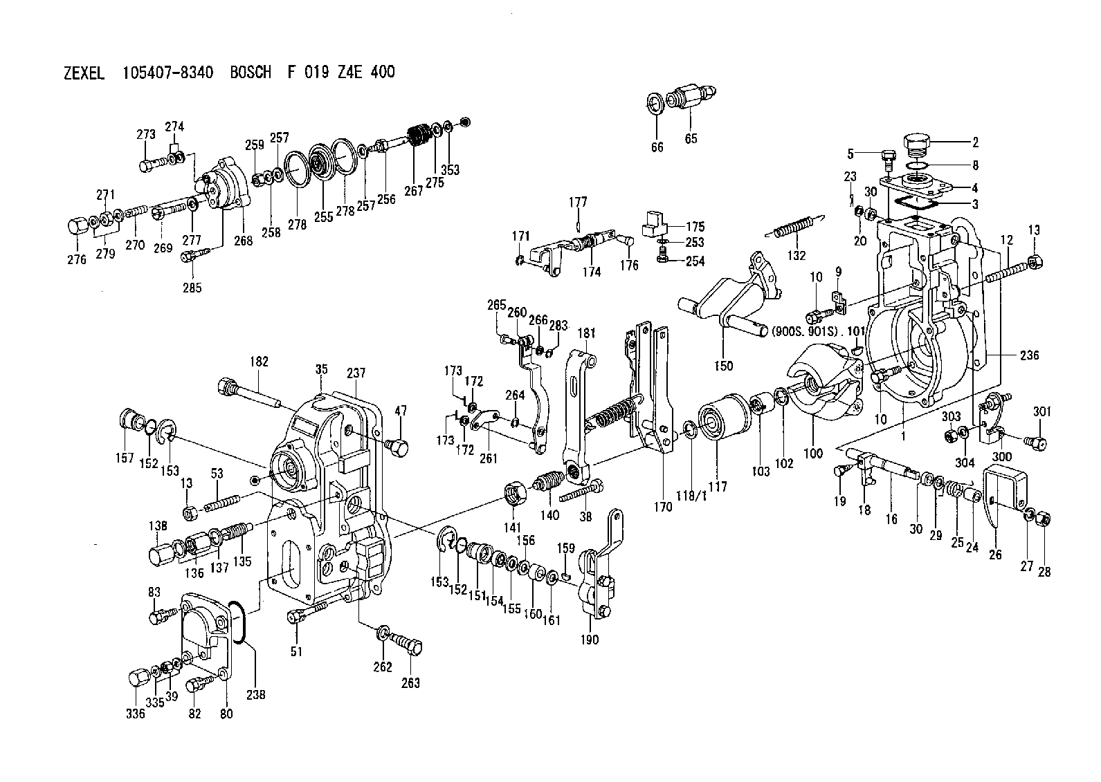
| 1. | [1] | 154004-2822 | GOVERNOR HOUSING |
| 2. | [1] | 154007-2900 | CAPSULE |
| 3. | [1] | 154358-2500 | SEAL RING |
| 4. | [1] | 154064-4500 | COVER |
| 5. | [4] | 020006-1640 | BLEEDER SCREW |
| 8. | [1] | 029632-5070 | O-RING |
| 9. | [1] | 154350-6000 | PLATE |
| 10. | [8] | 020106-2040 | BLEEDER SCREW |
| 10. | [8] | 020106-2040 | BLEEDER SCREW |
| 12. | [1] | 154010-0100 | FLAT-HEAD SCREW |
| 13. | [2] | 154011-0100 | HEXAGON NUT |
| 13. | [2] | 154011-0100 | HEXAGON NUT |
| 16. | [1] | 155004-3600 | LEVER SHAFT |
| 18. | [1] | 155003-2101 | CONTROL LEVER |
| 19. | [1] | 155006-0700 | BLEEDER SCREW |
| 20. | [1] | 139308-0900 | PLAIN WASHER D16&8T1 |
| 20B. | [1] | 139308-1000 | PLAIN WASHER D16&8T1.5 |
| 20C. | [1] | 139408-1500 | SHIM D16&8T0.5 |
| 23. | [1] | 025520-1210 | SPLIT PIN |
| 24. | [1] | 154206-6300 | BUSHING |
| 25. | [1] | 154327-4200 | COILED SPRING |
| 26. | [1] | 154381-7900 | CONTROL LEVER |
| 27. | [1] | 014110-8440 | LOCKING WASHER D15.4&8.2T2 |
| 28. | [1] | 013020-8040 | UNION NUT |
| 29. | [1] | 139408-1500 | SHIM D16&8T0.5 |
| 29B. | [0] | 139408-1400 | SHIM D16&8T0.2 |
| 29C. | [0] | 139408-1500 | SHIM D16&8T0.5 |
| 30. | [2] | 029620-8050 | PACKING RING |
| 30. | [2] | 029620-8050 | PACKING RING |
| 35. | [1] | 154022-7920 | GOVERNOR COVER |
| 38. | [1] | 154031-1300 | FLAT-HEAD SCREW |
| 39. | [1] | 139206-0600 | UNION NUT |
| 47. | [1] | 154036-0300 | CAPSULE |
| 51. | [6] | 020106-5040 | BLEEDER SCREW |
| 53. | [1] | 154010-0200 | FLAT-HEAD SCREW |
| 65. | [1] | 153021-2220 | STOPPING DEVICE |
| 66. | [1] | 026524-3040 | GASKET |
| 80. | [1] | 154063-1400 | COVER |
| 82. | [2] | 029020-6210 | BLEEDER SCREW |
| 83. | [2] | 020006-1640 | BLEEDER SCREW |
| 100. | [1] | 154101-0020 | FLYWEIGHT ASSEMBLY |
| 101. | [1] | 025803-1310 | WOODRUFF KEY 13 MM |
| 102. | [1] | 029321-2020 | LOCKING WASHER |
| 103. | [1] | 029231-2030 | UNION NUT |
| 117. | [1] | 154123-2320 | SLIDING PIECE |
| 118/1. | [0] | 029311-0010 | SHIM D14&10.1T0.2 |
| 118/1. | [0] | 029311-0180 | SHIM D14&10.1T0.3 |
| 118/1. | [0] | 029311-0190 | SHIM D14&10.1T0.40 |
| 118/1. | [0] | 029311-0210 | SHIM D14&10.1T1 |
| 118/1. | [0] | 139410-0000 | SHIM D14&10.1T0.5 |
| 118/1. | [0] | 139410-0100 | SHIM D14&10.1T1.5 |
| 118/1. | [0] | 139410-3000 | SHIM D14&10.1T2.0 |
| 118/1. | [0] | 139410-3100 | SHIM D14&10.1T3.0 |
| 118/1. | [0] | 139410-3200 | SHIM D14&10.1T4.0 |
| 132. | [1] | 154154-0500 | COILED SPRING |
| 135. | [1] | 154158-0820 | HEADLESS SCREW |
| 136. | [1] | 029201-2290 | UNION NUT |
| 137. | [2] | 026512-1540 | GASKET |
| 138. | [1] | 154159-1200 | CAP NUT |
| 140. | [1] | 154185-3920 | HEADLESS SCREW |
| 141. | [1] | 029201-6010 | UNION NUT |
| 150. | [1] | 154200-6920 | SWIVELLING LEVER |
| 151. | [1] | 154204-4300 | BUSHING |
| 152. | [2] | 029631-8020 | O-RING |
| 152. | [2] | 029631-8020 | O-RING |
| 153. | [2] | 016010-1640 | LOCKING WASHER |
| 153. | [2] | 016010-1640 | LOCKING WASHER |
| 154. | [1] | 139611-0000 | PACKING RING |
| 155. | [1] | 139411-0000 | SHIM |
| 156. | [0] | 029311-1070 | SHIM D16&11T0.5 |
| 157. | [1] | 154204-4400 | BUSHING |
| 159. | [1] | 025803-1310 | WOODRUFF KEY 13 MM |
| 160. | [1] | 154206-2800 | BUSHING |
| 161. | [0] | 154206-0200 | PLAIN WASHER D19.5&11.2T1.0 |
| 170. | [1] | 154217-2920 | FORK LEVER |
| 171. | [1] | 016010-0540 | LOCKING WASHER |
| 172. | [3] | 029310-5170 | SHIM |
| 172. | [3] | 029310-5170 | SHIM |
| 173. | [2] | 025520-1210 | SPLIT PIN |
| 173. | [2] | 025520-1210 | SPLIT PIN |
| 174. | [1] | 154235-5020 | STRAP |
| 175. | [1] | 154232-2420 | CONNECTOR |
| 176. | [1] | 159231-4900 | BEARING PIN |
| 177. | [1] | 155402-3800 | SAFETY PIN |
| 181. | [1] | 154239-3320 | TENSIONING LEVER |
| 182. | [1] | 154237-1100 | BEARING PIN |
| 190. | [1] | 154347-1920 | CONTROL LEVER |
| 236. | [1] | 154371-5600 | GASKET |
| 237. | [1] | 154390-0300 | GASKET |
| 238. | [1] | 029635-2020 | O-RING |
| 253. | [1] | 029320-5020 | LOCKING WASHER |
| 254. | [1] | 010535-1040 | FLAT-HEAD SCREW |
| 255. | [1] | 154400-7420 | DIAPHRAGM |
| 256. | [1] | 154400-4800 | STOP PIN |
| 257. | [2] | 029330-8050 | GASKET |
| 257. | [2] | 029330-8050 | GASKET |
| 258. | [1] | 139308-0700 | LOCKING WASHER |
| 259. | [1] | 013030-6040 | UNION NUT |
| 260. | [1] | 154401-3620 | CONTROL LEVER |
| 261. | [1] | 154401-1320 | STRAP |
| 262. | [1] | 026510-1440 | GASKET |
| 263. | [1] | 154401-2100 | BLEEDER SCREW |
| 264. | [1] | 016010-0540 | LOCKING WASHER |
| 265. | [1] | 154222-6200 | BEARING PIN |
| 266. | [1] | 029300-4010 | PLAIN WASHER |
| 267. | [1] | 154411-8100 | COILED SPRING |
| 268. | [1] | 154404-5000 | COVER |
| 269. | [2] | 020106-2540 | BLEEDER SCREW |
| 270. | [1] | 154034-1900 | FLAT-HEAD SCREW |
| 271. | [1] | 013030-6040 | UNION NUT |
| 273. | [1] | 029731-0180 | EYE BOLT |
| 274. | [2] | 026510-1340 | GASKET |
| 275. | [0] | 029312-0180 | SHIM D25.5&20T0.5 |
| 275B. | [0] | 029312-0210 | SHIM D25.5&20T0.2 |
| 276. | [1] | 154035-1900 | CAP NUT |
| 277. | [1] | 014110-6440 | LOCKING WASHER D12.2&6.1T1.5 |
| 278. | [2] | 154413-2600 | GASKET |
| 278. | [2] | 154413-2600 | GASKET |
| 279. | [2] | 026506-1040 | GASKET |
| 283. | [1] | 016010-0440 | LOCKING WASHER |
| 285. | [1] | 029010-6310 | BLEEDER SCREW |
| 300. | [1] | 154358-9420 | BRACKET |
| 301. | [1] | 020118-1640 | BLEEDER SCREW |
| 303. | [1] | 154011-1100 | UNION NUT |
| 304. | [1] | 029300-8320 | SHIM |
| 335. | [2] | 026506-1040 | GASKET |
| 336. | [1] | 154035-1600 | CAP NUT |
| 353. | [3] | 029310-9080 | SHIM |
| 900S. | [1] | 025803-1310 | WOODRUFF KEY 13 MM |
| 901S. | [1] | 025803-1610 | WOODRUFF KEY 16 MM |
Include in #1:
106676-2770
as GOVERNOR
Cross reference number
Zexel num
Bosch num
Firm num
Name
ME755955 MITSUBISHI
GOVERNOR
* K 14JB MECHANICAL GOVERNOR GOV RSV GOV
* K 14JB MECHANICAL GOVERNOR GOV RSV GOV
Information:
2. Turn the crankshaft until two pistons are at bottom center.3. Remove bolts (1) and the bearing caps. Push the rods and pistons up until the rings are out of the cylinder liners. 4. Remove pistons (2) and connecting rods from the cylinder liners.5. Do Steps 1 through 4 for the remainder of the pistons and connecting rods.Install Pistons & Connecting Rod Assemblies
1. Put clean engine oil on piston rings, connecting rod bearings and cylinder liners. 2. Use Tool (A), and install piston (2) and the connecting rod in the cylinder liner.3. Install the bearing cap on the connecting rod with the number on the side of the bearing cap on the same side and same number as on the connecting rod.4. Put 2P2506 Thread Lubricant on the threads of the bolts. Install the nuts, and tighten them to a torque of 90 8 N m (67 6 lb ft). Put a mark on the nuts and cap, and tighten the nuts an extra 90 5 degrees.5. Do Steps 1 through 4 for the remainder of the pistons and connecting rods.End By:a. install piston cooling tubesb. install oil pumpc. install cylinder head assemblyDisassemble & Assemble Pistons & Connecting Rod Assemblies
Start By:a. remove pistons and connecting rod assemblies 1. Remove bearings (3) from the connecting rod and connecting rod cap.2. Remove retainer ring (1) with Tool (A).3. Remove pin (2) and connecting rod (4) from the piston. 4. Remove piston rings (5) from the piston with Tool (B). Clean the piston ring grooves on the pistons with an acceptable ring groove cleaning tool. See, Use Of Piston Bearing Removal And Installation Tools, Special Instructions, SMHS7295.5. Heat connecting rod (4) in an oven to a temperature of 177° to 260°C (350° to 500° F). Never use a direct flame to heat a connecting rod. 6. Put connecting rod (4) in position on the base plate of Tool (C). Put a new rod pin bearing (6) on the adapter part of Tool (C). The old bearing is pushed out by Tool (C) as the new bearing is installed.7. Use Tool (C) to push the new bearing into the connecting rod until the push adapter of Tool (C) makes full contact with the connecting rod surface.8. Use a pin boring machine to make the rod pin bearing the correct size. The bore in the new rod pin bearing must be 50.830 0.008 mm (2.0012 .0003 in).9. Check the clearance between the ends of the piston rings. See the topic, "Pistons & Rings" in Specifications Manual, SENR6470.10. Install the oil ring spring in the oil ring groove of the piston. The oil ring is to be installed over the spring with the oil ring end gap 180° from the oil ring spring joint.11. Install the oil ring on the piston with tool (B).12. Install the second (intermediate) piston ring with the side that has the identification "UP-2" toward the top of the piston. Use Tool (B) to install