Information governor
BOSCH
9 420 614 520
9420614520
ZEXEL
105407-7380
1054077380
HINO
223204600A
223204600a
Rating:
Scheme ###:
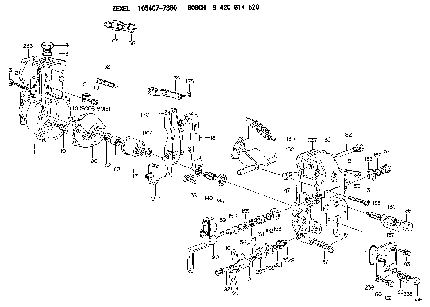
| 1. | [1] | 154000-4700 | GOVERNOR HOUSING |
| 3. | [1] | 029632-5070 | O-RING |
| 4. | [1] | 154007-2900 | CAPSULE |
| 9. | [1] | 154350-6000 | PLATE |
| 10. | [8] | 020106-2040 | BLEEDER SCREW M6P1L20 |
| 10. | [8] | 020106-2040 | BLEEDER SCREW M6P1L20 |
| 12. | [1] | 154010-1100 | FLAT-HEAD SCREW |
| 13. | [2] | 154011-0100 | HEXAGON NUT |
| 13. | [2] | 154011-0100 | HEXAGON NUT |
| 35. | [1] | 154500-8120 | GOVERNOR COVER |
| 35/2. | [1] | 154321-0400 | BUSHING |
| 38. | [1] | 154031-4300 | FLAT-HEAD SCREW |
| 39. | [1] | 139208-0400 | UNION NUT |
| 47. | [1] | 154036-0300 | CAPSULE |
| 51. | [2] | 020106-5040 | BLEEDER SCREW |
| 53. | [1] | 154010-0100 | FLAT-HEAD SCREW |
| 56. | [4] | 020106-3840 | BLEEDER SCREW |
| 65. | [1] | 153021-2220 | STOPPING DEVICE |
| 66. | [1] | 026524-3040 | GASKET |
| 80. | [1] | 154063-7300 | COVER |
| 82. | [2] | 029020-6210 | BLEEDER SCREW |
| 83. | [2] | 020006-1640 | BLEEDER SCREW M6P1L16 4T |
| 100. | [1] | 154101-0020 | FLYWEIGHT ASSEMBLY |
| 101. | [1] | 025803-1310 | WOODRUFF KEY |
| 102. | [1] | 029321-2020 | LOCKING WASHER |
| 103. | [1] | 029231-2030 | UNION NUT |
| 117. | [1] | 154123-2320 | SLIDING PIECE |
| 118/1. | [0] | 029311-0010 | SHIM D14&10.1T0.2 |
| 118/1. | [0] | 029311-0180 | SHIM D14&10.1T0.3 |
| 118/1. | [0] | 029311-0190 | SHIM D14&10.1T0.40 |
| 118/1. | [0] | 029311-0210 | SHIM D14&10.1T1 |
| 118/1. | [0] | 139410-0000 | SHIM D14.0&10.1T0.5 |
| 118/1. | [0] | 139410-0100 | SHIM D14.0&10.1T1.5 |
| 118/1. | [0] | 139410-3000 | SHIM D14&10.1T2.0 |
| 118/1. | [0] | 139410-3100 | SHIM D14&10.1T3.0 |
| 118/1. | [0] | 139410-3200 | SHIM D14&10.1T4.0 |
| 130. | [1] | 154151-0800 | GOVERNOR SPRING |
| 132. | [1] | 154154-0500 | COILED SPRING |
| 135. | [1] | 154158-1320 | HEADLESS SCREW |
| 136. | [1] | 154011-2700 | UNION NUT |
| 137. | [2] | 026512-1540 | GASKET D15.4&12.2T1.50 |
| 138. | [1] | 154159-1200 | CAP NUT |
| 140. | [1] | 154185-1320 | HEADLESS SCREW |
| 141. | [1] | 029201-6010 | UNION NUT |
| 150. | [1] | 154200-7020 | SWIVELLING LEVER |
| 151. | [1] | 154204-4300 | BUSHING |
| 152. | [2] | 029631-8020 | O-RING |
| 152. | [2] | 029631-8020 | O-RING |
| 153. | [2] | 016010-1640 | LOCKING WASHER |
| 153. | [2] | 016010-1640 | LOCKING WASHER |
| 154. | [1] | 139611-0000 | PACKING RING |
| 155. | [1] | 139411-0000 | SHIM |
| 156. | [0] | 029311-1070 | SHIM D16&11T0.5 |
| 157. | [1] | 154204-4400 | BUSHING |
| 159. | [1] | 025803-1310 | WOODRUFF KEY |
| 160. | [1] | 154206-2800 | BUSHING |
| 161. | [0] | 154206-0200 | PLAIN WASHER D19.5&11.2T1.0 |
| 170. | [1] | 154210-2720 | FORK LEVER |
| 174. | [1] | 154230-2920 | STRAP |
| 175. | [1] | 016010-0540 | LOCKING WASHER |
| 181. | [1] | 154236-4100 | TENSIONING LEVER |
| 182. | [1] | 154237-1100 | BEARING PIN |
| 190. | [1] | 154343-0220 | CONTROL LEVER |
| 191. | [1] | 154381-5620 | CONTROL LEVER |
| 192. | [1] | 020006-3540 | BLEEDER SCREW |
| 201. | [1] | 029631-0030 | O-RING &9.8W2.3 |
| 203. | [1] | 154322-0100 | CAP |
| 207. | [1] | 154326-5020 | CONTROL LEVER |
| 208. | [1] | 154327-7600 | COILED SPRING |
| 211/1. | [0] | 029311-0520 | SHIM D20.8&10.3T0.2 |
| 211/1. | [0] | 029311-0530 | SHIM D20.8&10.3T0.25 |
| 211/1. | [0] | 029311-0540 | SHIM D20.8&10.3T0.3 |
| 211/1. | [0] | 029311-0550 | SHIM D20.8&10.3T0.35 |
| 211/1. | [0] | 029311-0560 | SHIM D20.8&10.3T0.4 |
| 211/1. | [0] | 029311-0570 | SHIM D20.8&10.3T0.5 |
| 236. | [1] | 154371-5600 | GASKET |
| 237. | [1] | 154390-0300 | GASKET |
| 238. | [1] | 029635-2020 | O-RING |
| 335. | [2] | 026508-1140 | GASKET D11.4&8.2T1 |
| 336. | [1] | 154035-2000 | CAP NUT |
| 900S. | [1] | 025803-1310 | WOODRUFF KEY |
| 901S. | [1] | 025803-1610 | WOODRUFF KEY |
Cross reference number
Zexel num
Bosch num
Firm num
Name
105407-7380
223204600A HINO
GOVERNOR
K 14JB MECHANICAL GOVERNOR GOV RSV GOV
K 14JB MECHANICAL GOVERNOR GOV RSV GOV
Information:
Governor Linkage Adjustment
(1) Rod. (2) Nut. (3) Control lever. (4) Lever. (5) Pin. (6) High idle stop. (7) Locknut. (8) Low idle stop. (9) Locknut. (10) Decelerator treadle. (11) Floor plate. (12) Accelerator treadle. (13) Lever. (14) Rod. (15) Locknut. (16) Lever. (17) Locknut. (A) 9.7 mm (.38 in). (B) 4.8 mm (.19 in). (C) 38.1 mm (1.50 in). (D) 60.5 3.0 mm (2.38 .12 in). DO NOT USE control lever (3), or decelerator treadle (10) to shut OFF the engine.To shut engine OFF, pull up on accelerator treadle (12).1. Tighten nut (2) just enough so position of control lever (3) is not affected by the operation of the accelerator treadle (12) and decelerator treadle (10).2. With the parking brake ON and engine stopped, BE SURE disconnect switch is OFF.3. Remove pin (5).4. Loosen LOW IDLE stop (8) and HIGH IDLE stop (6) so they do not touch lever (13).5. Move control lever (3) to LOW IDLE position.6. Turn LOW IDLE stop (8) until it touches lever (13) and tighten locknut (9).7. Adjust length of rod (14) so distance from top of lever (16) to bottom of floor plate (11) is (C) 38.1 mm (1.50 in) as shown.8. Loosen locknut (15) and adjust length of rod so top of decelerator treadle (10) is (B) 4.8 mm (.19 in) above floor plate (11) as shown. If machine is equipped with a thick floor insulation pad, (used with enclosed cab), adjust decelerator treadle (10) so top of treadle is (A) 9.7 mm (.38 in) above top of floor plate and tighten locknut (15).9. Move control lever (3) to HIGH IDLE position.10. Turn HIGH IDLE stop (6) until it touches lever (13) and tighten locknut (7).11. Loosen locknut (17) and adjust accelerator treadle (12) so that distance from bottom of plate on treadle to top of floor plate (11) is (D) 60.5 3.0 mm (2.38 .12 in) as shown.12. Move lever (4) to HIGH IDLE position and adjust length of rod (1) so pin (5) can be installed.13. Install pin (5).
DO NOT adjust the linkage so the treadle can be used to shut off the engine. If the operator is in a standing position and places a foot on the treadle, the engine could be unexpectedly shut off, creating a situation where the machine can be difficult to control.
518 Skidder
1. Move governor shaft (3) to SHUT OFF position and install lever (2) on shaft (3) at angle (A).2. Adjust length of rod (5) so stop (4) on pedal (1) is at dimension (B) from the floor plate.Angle (A) ... 35 5°Dimension (B) ... 67 1 mm (2.64 .01 in)3. Tighten nut (6) ... 12 4 N m (9 3 lb ft)D5H
1. Move governor lever (2) to high idle and install spring (6). Move governor lever (2) to vertical position and adjust stop bolt (3) to contact lever (2), back off one turn and lock.2. Position lever (9) on the splined governor shaft